A switching device

A switching device and device technology, applied in the field of improving the switching device, can solve the problems of increasing the time and cost of the switching device, reducing the service life of the electric contact of the pole, etc.

Active Publication Date: 2018-04-17
ABB (SCHWEIZ) AG
View PDF8 Cites 4 Cited by
  • Summary
  • Abstract
  • Description
  • Claims
  • Application Information

AI Technical Summary

Problems solved by technology

[0016] Since said micro-arcing significantly reduces the service life of the electrical contacts of the pole, it is often necessary to cover

Method used


Image

  • A switching device
  • A switching device
  • A switching device

Examples


Embodiment Construction

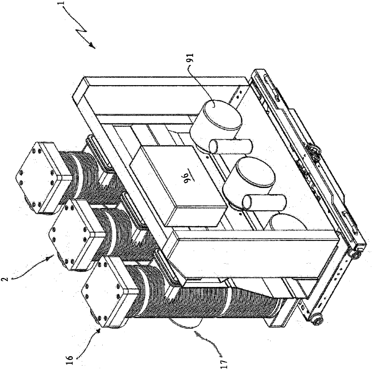
[0027] With reference to the cited figures, the invention relates to a switching device 1 .

[0028] The switching device 1 is particularly suitable for use in MV power distribution networks and will be described below with reference to this particular application. However, the switching device 1 can also be conveniently used in LV power distribution networks.

[0029] The switching device 1 is adapted to electrically connect / disconnect a power line 101 with one or more associated electrical loads 102 .

[0030] The switching device 1 is particularly useful for use in power distribution networks feeding capacitive loads, and will be described hereinafter with reference to this particular application. However, in principle, the electrical load 102 can be of any type according to need.

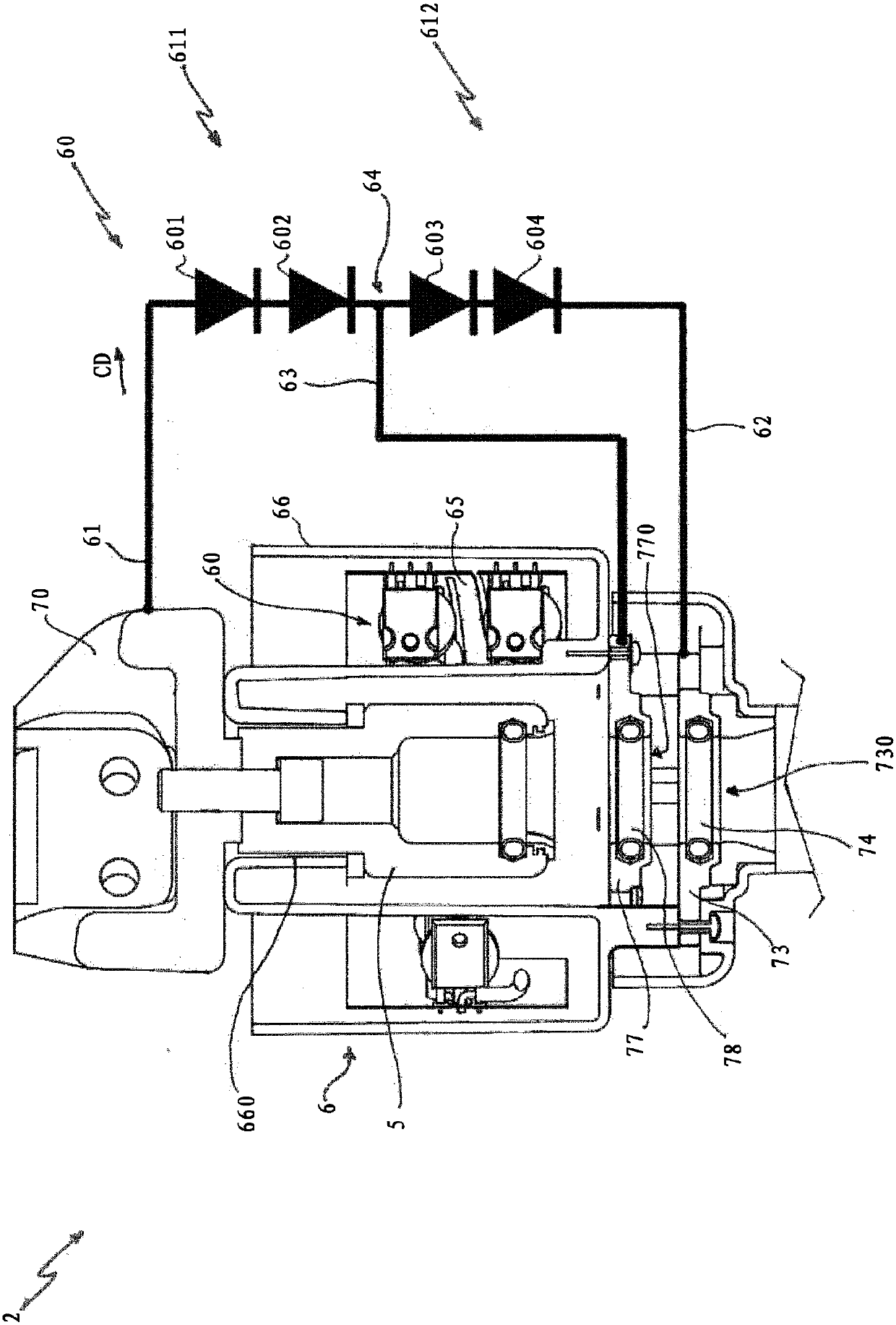
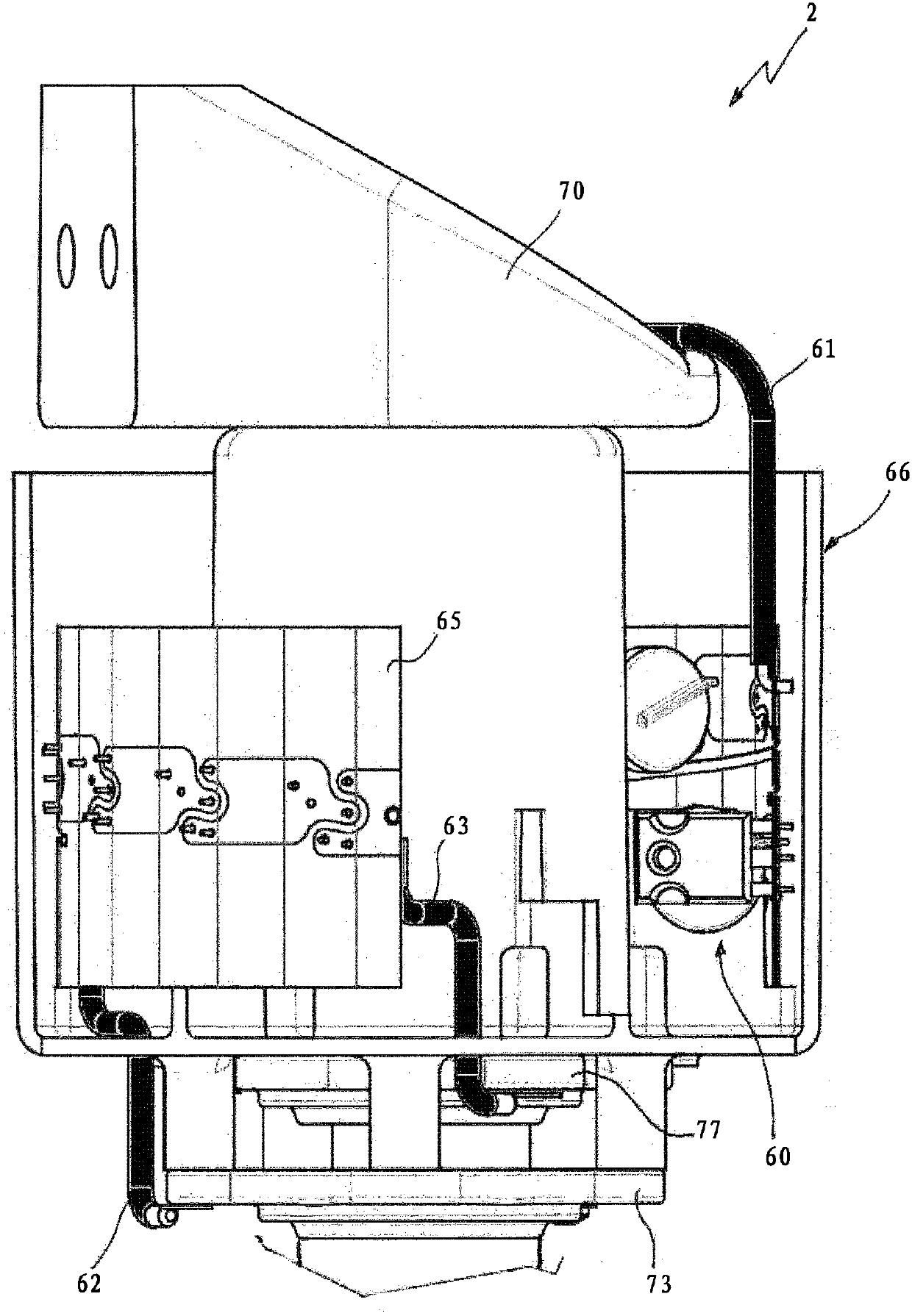
[0031] Switching device 1 comprises one or more poles 2 (for example figure 1 three poles shown in ), wherein each pole 2 is electrically connected to a corresponding electrical phase of the ...


PUM


Abstract

A switching device (1) for low or medium voltage electric power distribution networks, said switching device comprising: - at least an electric pole (2) comprising a movable contact (4) and a fixed contact (5), which are coupleable/decoupleable one to another; - a circuit assembly (6), which comprises a chain (60) of semiconductor devices (601, 602, 603, 604, 605, 606) adapted to switch in an ON state or in an OFF state depending on the voltage applied thereto, said semiconductor devices being electrically connected in series one to another in such a way that a current can flow according to apredefined conduction direction (CD) when said semiconductor devices are in an ON state. The circuit assembly (6) comprises an input terminal (61), an output terminal (62) and at least an intermediateterminal (63) electrically connected with at least an intermediate electric node (64) positioned between two subsequent semiconductor devices (602, 603, 604, 605). The input terminal (61) is electrically connected with said fixed contact: The input terminal (61), the output terminal (62) and the at least an intermediate terminal (63) are electrically coupleable/decoupleable with/from said movablecontact (4) when said movable contact reaches different positions (P1, P2, P3, P4) during a movement towards/away from said fixed contact (5) in such a way that different groups (611, 612) of semiconductor devices switch in an ON state or in an OFF state at different instants (t2, t3, t4, t6, t7, t8) during the movement of said movable contact, depending on the position reached by said movable contact.

Description

technical field [0001] The invention relates to the field of switchgear for low or medium voltage distribution networks. [0002] More specifically, the present invention relates to improved switching devices for use in medium or low voltage distribution networks. [0003] In another aspect, the present invention relates to a switching device comprising the switching device described above. Background technique [0004] Within the framework of the present invention, the term "low voltage" (LV) relates to nominal operating voltages below 1kV AC and 1.5kV DC, while the term "medium voltage" (MV) relates to nominal operating voltages above 1kV AC and 1.5kV DC up to tens of Nominal working voltage in kV (for example, up to 72kV AC and 100kVDC). [0005] As is known, switching devices are installed in power distribution networks for connecting / disconnecting power lines with one or more associated electrical loads. [0006] A conventional switching device includes one or more e...

Claims


Application Information

Patent Timeline
IPC IPC(8): H01H9/54H01H9/56
CPCH01H9/542H01H9/56H01H9/30H01H9/54H05K1/028H05K1/181H05K2201/051H05K2201/10053H05K2201/10174
Inventor A·比安科C·博费利P·福尔拉加尼R·彭佐
Owner ABB (SCHWEIZ) AG
Why Eureka
Try Eureka