Organic electroluminescent element, display device, and illumination device
一种电致发光元件、致发光的技术,应用在照明装置、发光元件的半导体器件、电气元件等方向,能够解决硼的化合物不稳定等问题
- Summary
- Abstract
- Description
- Claims
- Application Information
AI Technical Summary
Problems solved by technology
Method used
Image

Examples
Embodiment approach
[0514] One Embodiment of the illuminating device of this invention provided with the organic EL element of this invention is demonstrated.
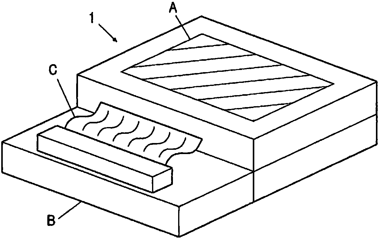
[0515] The non-light-emitting surface of the organic EL element of the present invention was covered with a glass case, a glass substrate with a thickness of 300 μm was used as a substrate for sealing, and an epoxy-based photocurable adhesive (LUXTRACK LC0629B, manufactured by Toa Gosei Co., Ltd.) was applied as a sealing material around it. , it is superimposed on the cathode and closely adhered to the transparent support substrate, and UV light is irradiated from the glass substrate side to cure and seal it, so as to form Figure 7 and Figure 8 lighting fixture shown.
[0516] Figure 7 A schematic diagram showing a lighting device, the organic EL element (organic EL element 101 in the lighting device) of the present invention is covered with a glass cover plate 102 (it should be noted that the sealing operation in the glass cover pl...
Embodiment 1
[0531] 1. Fabrication of organic EL elements
[0532]An organic EL element was produced using the following compounds as electron transport layer materials.
[0533] [Chemical formula 30]
[0534]
[0535] [Chemical formula 31]
[0536]
[0537] [Chemical formula 32]
[0538]
[0539] (Production of Organic EL Element 1-1)
[0540] Patterning was performed on a substrate (manufactured by Avan Strate Co., Ltd., NA-45) in which ITO (indium tin oxide) as an anode was formed into a film of 100 nm on a glass substrate of 100 mm×100 mm×1.1 mm. Then, the transparent support substrate on which the ITO transparent electrode was provided was ultrasonically cleaned with isopropyl alcohol, dried with dry nitrogen, and UV ozone cleaning was performed for 5 minutes.
[0541] On this transparent support substrate, poly(3,4-ethylenedioxythiophene)-polystyrenesulfonate (PEDOT / PSS (hole transport material 1), manufactured by Bayer Co., Ltd., Baytron P Al4083) was used. The solutio...
Embodiment 2
[0565] An organic EL element was produced using the following compounds as host materials.
[0566] [Chemical formula 34]
[0567]
[0568] [Chemical formula 35]
[0569]
[0570] [Chemical formula 36]
[0571]
[0572] (Production of Organic EL Element 2-1)
[0573] On a glass substrate of 50 mm×50 mm×thickness 0.7 mm, ITO (indium tin oxide) was formed into a film with a thickness of 150 nm, and then patterned to form an ITO transparent electrode as an anode. The transparent substrate provided with the ITO transparent electrode was ultrasonically cleaned with isopropyl alcohol, dried with dry nitrogen, and then cleaned with UV ozone for 5 minutes. The obtained transparent substrate was fixed to the substrate holder of a commercially available vacuum vapor deposition apparatus.
[0574] Each of the resistive heating boats for vapor deposition in the vacuum vapor deposition apparatus is filled with each layer constituting material in an amount most suitable for pro...
PUM
| Property | Measurement | Unit |
|---|---|---|
| energy level | aaaaa | aaaaa |
| glass transition temperature | aaaaa | aaaaa |
| coating thickness | aaaaa | aaaaa |
Abstract
Description
Claims
Application Information
 - Generate Ideas
- Intellectual Property
- Life Sciences
- Materials
- Tech Scout
- Unparalleled Data Quality
- Higher Quality Content
- 60% Fewer Hallucinations
Browse by: Latest US Patents, China's latest patents, Technical Efficacy Thesaurus, Application Domain, Technology Topic, Popular Technical Reports.
© 2025 PatSnap. All rights reserved.Legal|Privacy policy|Modern Slavery Act Transparency Statement|Sitemap|About US| Contact US: help@patsnap.com