
Aluminum alloy thin plate T-joint laser welding robot arm end welding execution end

A laser welding, aluminum alloy technology, applied in laser welding equipment, welding/welding/cutting items, welding equipment, etc., can solve the problem of few adjustment methods of wire feeding tube and air feeding tube, poor adjustment accuracy of wire feeding tube and air feeding end, The problems of low installation and uninstallation efficiency have achieved the effect of wide applicability, guaranteed stability, and convenient installation, maintenance, operation and use.

Inactive Publication Date: 2019-08-13
TIANJIN UNIV
View PDF6 Cites 0 Cited by
  • Summary
  • Abstract
  • Description
  • Claims
  • Application Information

AI Technical Summary

Problems solved by technology

[0005] In view of the deficiencies in the current double-beam laser welding execution end, such as poor overall flexibility, limited scope of application, poor adjustment of wire feed tube and gas supply end, less adjustment methods of wire feed tube and gas supply tube, installation and unloading efficiency Low, insufficient automation capabilities, etc., develop a welding execution end that meets the conditions of the double-beam laser welding process, and research an execution end with the following functions:

Method used


Image

  • Aluminum alloy thin plate T-joint laser welding robot arm end welding execution end
  • Aluminum alloy thin plate T-joint laser welding robot arm end welding execution end
  • Aluminum alloy thin plate T-joint laser welding robot arm end welding execution end

Examples


example

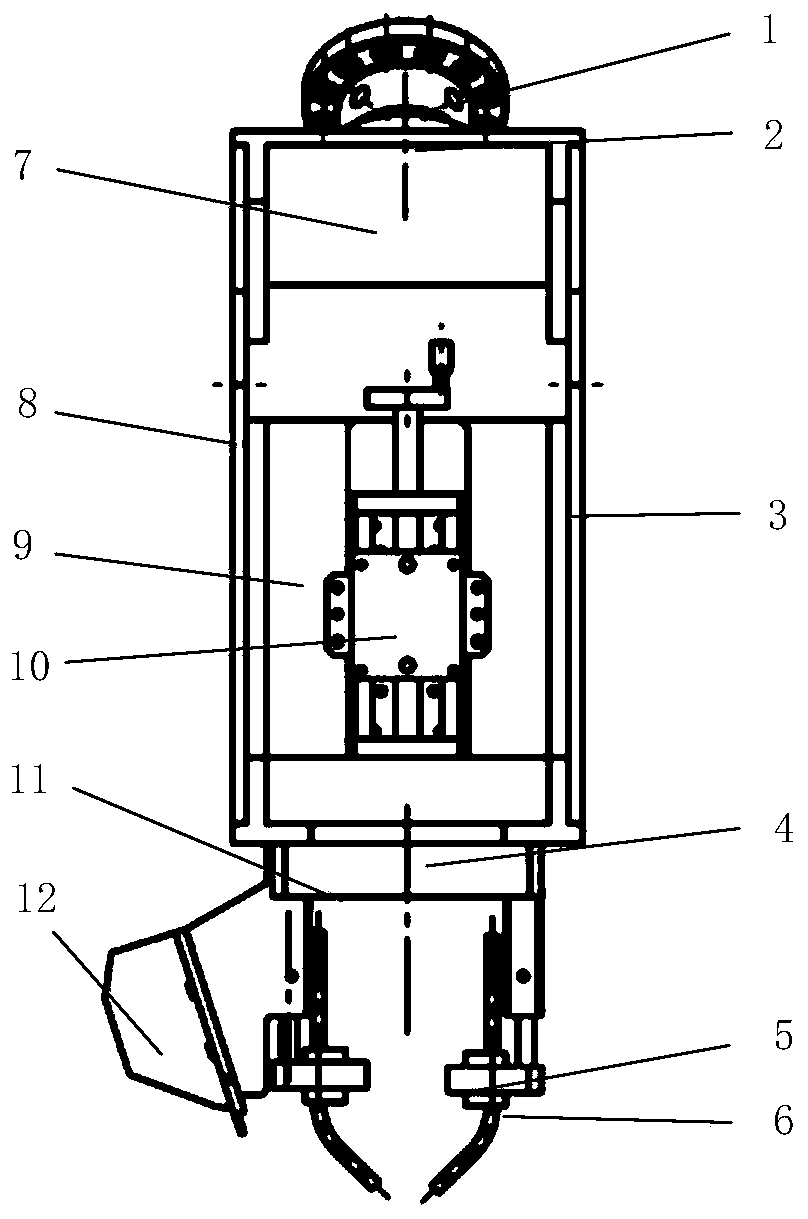
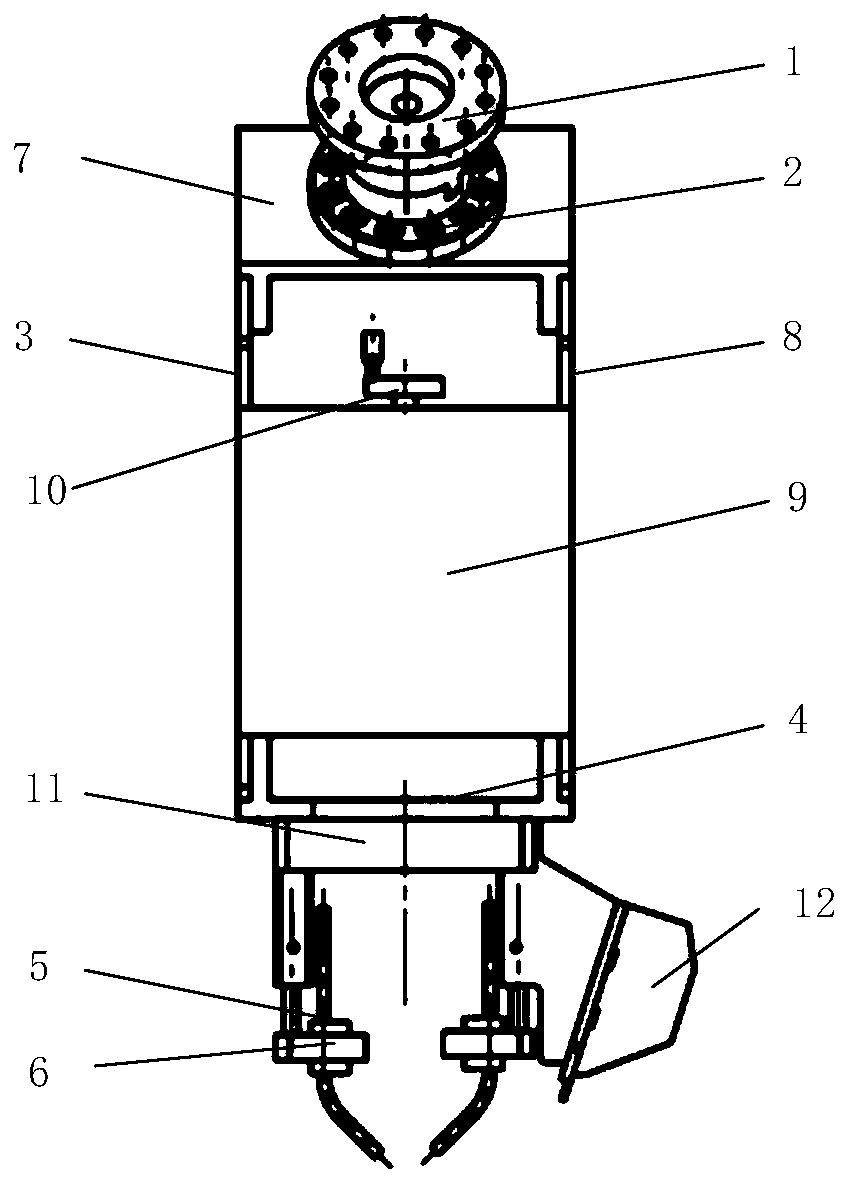
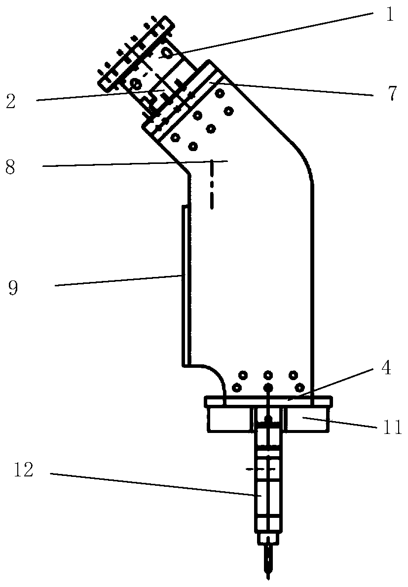
[0053] Utilize the welding execution end of the present invention and adopt the robot arm to realize the laser welding process, the robot selects the KUKAkr120 model, fully utilizes the flexibility of the robot arm to expand the application range of the welding execution end, Figure 5 It shows that the welding execution end of the present invention is compact in shape and has fewer parts. The welding execution end is mainly used for the double-beam laser welding process. This process needs to use the synchronous operation of the robot to form a welding posture with a certain angle that is symmetrical on both sides. At this time, in order to avoid The robot arm interferes, and the left and right side wall plates in the welding execution end are designed to have a certain angle, such as image 3 As shown, it is convenient to adjust the posture of the robot. At the same time, in order to improve the efficiency of the installation and disassembly of the welding execution end and ...


PUM

PropertyMeasurementUnit
thicknessaaaaaaaaaa

Abstract

The invention discloses a welding execution terminal of the boom end of a laser welding robot for T-shaped joints of aluminum alloy sheets. The welding execution terminal comprises a framework, a quick coupling on the top of the framework, and a gas supplying and wire feeding support. The framework comprises wing plates on the left side and the right side and a backboard. A hand sliding table is fixed to the backboard. The quick coupling comprises an adapting convex end and an adapting concave end which are in butt joint, and alignment is accurate and quick. The gas supplying and wire feedingsupport can achieve wire feeding and gas supplying and has one degree of freedom of rotation and three degrees of freedom of horizontal movement, and the front end of the gas supplying and wire feeding support is provided with a position sensor for tracking the welding joint. According to the welding execution terminal, the overall flexibility is high, the application range is wide, and a wire feeding pipe and a gas supplying pipe are convenient to adjust and high in precision; mounting and demounting are quick and the degree of automation is high; and the wire feeding position and the gas supplying structure in welding of a T-shaped joint are located in front of and behind a welding pool separately, and the wire feeding position, the gas supplying structure and the welding pool are located in the same plane, so that sliding positioning is achieved, the technical condition of dual-beam laser welding can be met, and the welding quality is ensured.

Description

technical field [0001] The invention belongs to the field of robot laser welding of thin plate structures, in particular to the welding execution end of double-beam laser welding aluminum alloy thin plate T-shaped joints. Background technique [0002] At present, in the field of aircraft manufacturing, dual-beam laser welding of fuselage panels is gradually being used to replace the traditional riveting connection process. Although the riveting process has the characteristics of high process stability, mature connection process, and high connection strength, it is also difficult to The structural structure is heavy and the production efficiency is low. At the same time, the riveting process requires prefabricated foundation holes on the stringers, which leads to poor structural integrity and reduced rigidity of the panel. The double-beam laser welding process has the advantages of high structural strength, small heat input, small welding deformation, high production efficien...

Claims


Application Information

Patent Timeline
Patent Type & Authority Patents(China)
IPC IPC(8): B23K26/21B23K26/70
CPCB23K26/21B23K26/702B23K2103/10
Inventor 李建波杨新岐陈俐何恩光
Owner TIANJIN UNIV
Learn More