Sensor with contact-pressing and ultrasonic functions

A sensor and touch pressure technology, applied in the field of sensors, can solve problems such as poor sensitivity, achieve good practicability, improve sensitivity, and increase complexity and difficulty.

Pending Publication Date: 2018-04-24
BEIJING SINO CANBRIDGE MED TECH CO LTD
View PDF10 Cites 4 Cited by
  • Summary
  • Abstract
  • Description
  • Claims
  • Application Information

AI Technical Summary

Problems solved by technology

Using ultrasound to detect palpable tissue lesions, especially solid tumors, will cause poor sensitivity and local ultrasound heat generation.

Method used


Image

  • Sensor with contact-pressing and ultrasonic functions
  • Sensor with contact-pressing and ultrasonic functions
  • Sensor with contact-pressing and ultrasonic functions

Examples


Embodiment 1

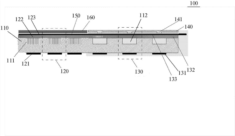
[0061] refer to figure 1, the present invention relates to a sensor 100 with touch pressure and ultrasonic functions, the sensor 100 includes a substrate 110 and an ultrasonic detection unit 120 and a touch pressure detection unit 130 formed on the substrate 110 .

[0062] The ultrasonic detection unit 120 includes a first ultrasonic detection electrode layer 121 formed on the lower surface of the substrate 110 and a first elastic film 122 and a second ultrasonic detection electrode layer 123 sequentially formed on the upper surface of the substrate 110 .

[0063] The touch detection unit 130 includes a first touch detection electrode layer 131 formed on the lower surface of the substrate 110, a second elastic film 132 and a second touch detection electrode layer sequentially formed on the upper surface of the substrate 110. electrode layer 133 .

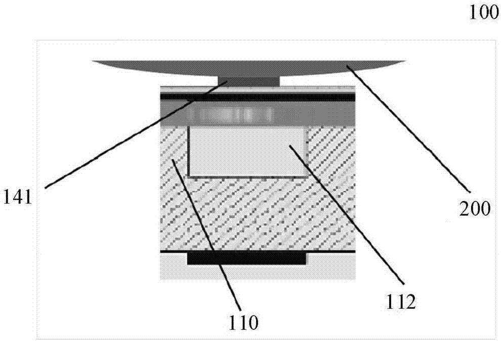
[0064] Wherein, the above-mentioned sensor 100 further includes a contact layer 140, the contact layer 140 corresponds to the to...

Embodiment 2

[0104] see Figure 6 , the present invention also discloses the preparation method of the sensor described in Example 1, specifically, including the following steps:

[0105] The first step is to prepare the upper plate.

[0106] For the upper plate, for example, a 4-inch SOI double-sided polished first silicon wafer 123 with a thickness of 300 μm is selected to make the upper plate part.

[0107] Through reverse coating, photolithography, and development of graphics, through the deep silicon etching process, etching penetrates the entire first silicon wafer to form alignment marks for bonding the upper plate during the bonding process.

[0108] The second step is to prepare the lower plate.

[0109] The lower plate is prepared, and the lower plate is, for example, a 4-inch second silicon wafer 110 with a thickness of 300 μm and polished on both sides. The lower plate is formed by the following steps:

[0110] Form an oxide layer of about 0.8 μm by thermal oxygen on both s...


PUM


Abstract

The invention discloses a sensor with contact-pressing and ultrasonic functions. The sensor comprises a substrate as well as an ultrasonic detection unit and a contact-pressing detection unit which are formed on the substrate; the ultrasonic detection unit comprises a first ultrasonic detection electrode layer formed on the lower surface of the substrate as well as a first elastic film and a second ultrasonic detection electrode layer which are formed on the upper surface of the substrate sequentially; the contact-pressing detection unit comprises a first contact-pressing detection electrode layer formed on the lower surface of the substrate as well as a second elastic film and a second contact-pressing detection electrode layer which are formed on the upper surface of the substrate sequentially; the sensor further comprises a contact layer; the contact layer corresponds to the contact-pressing detection unit and is formed on one side, far away from the substrate, of the second contact-pressing detection electrode layer; the contact layer comprises a contact bulge; the contact bulge faces to the second contact-pressing detection electrode layer. When an external force acts on the sensor, the contact bulge can transmit the external force to the second elastic film well, so that the second elastic film generate greater deformation and the sensitivity of the sensor is improved.

Description

technical field [0001] The invention relates to the technical field of sensors, in particular to a sensor with touch pressure and ultrasonic functions. Background technique [0002] The most common method of human examination of the body surface and palpable tissues is palpation. Using the pressure sensor array to simulate the tactile corpuscles arranged in the human skin for bionic palpation can realize the process of screening and detecting the abnormality of the tissue to be examined. [0003] The long-term reliability of the pressure sensor, temperature and humidity stability, repeatability, zero drift and other static characteristics, the thickness of the sensor and the mechanical properties of the force-sensitive material are all important factors affecting the performance of the pressure sensor. To detect the elastic pressure distribution, an array of the same single pressure sensor is required, and factors such as the homogeneity of each pressure sensor, the uniform...

Claims


Application Information

Patent Timeline
Patent Type & Authority Applications(China)
IPC IPC(8): G01D5/12G01D5/48A61B5/00A61B8/08
CPCA61B5/0053G01D5/12G01D5/48A61B8/0833A61B2562/00
Inventor 宋军华王洪超王晓琴陈金薄云峰
Owner BEIJING SINO CANBRIDGE MED TECH CO LTD
Why Eureka
Try Eureka