Supercharge Your Innovation With Domain-Expert AI Agents!

Boring, milling and grinding composite machining tool

A composite machining and machine tool technology, applied in the field of machine tools, can solve the problems of low machining accuracy of parts, difficult clamping, and low machining efficiency, and achieve the effects of improving the quality of the machined surface, improving the flexible machining ability, and improving the machining efficiency.

Inactive Publication Date: 2018-04-27
徐州傲扬自动化科技有限公司
View PDF0 Cites 0 Cited by
  • Summary
  • Abstract
  • Description
  • Claims
  • Application Information

AI Technical Summary

Problems solved by technology

[0003] When the hole diameter of the part is large, the inner hole and the outer circle of the workpiece are processed with a smaller diameter tool or grinding wheel, and the circular axis CNC interpolation method is usually used in the circumferential direction. The disadvantage of this processing method is that the roundness of the processed hole is low and the step hole is the same Axial accuracy is low
[0004] Generally, a lathe is used to process the outer circle or the outer cone, in which the tool remains still and the spindle is used to rotate and feed, the machining efficiency is low and the surface of the part is poor
When encountering large or long parts, it is easy to cause difficulty in clamping
Due to the large moment of inertia and low rotation accuracy of large parts, the processing accuracy of parts is low due to traditional turning. Therefore, a new method of keeping large parts fixed and cutting tools with rotating feed is studied.
[0005] The processing of complex parts generally includes multiple processes. Milling, boring, and grinding are respectively clamped and processed on different machine tools, which results in low processing positioning accuracy and low processing efficiency.

Method used


Image

  • Boring, milling and grinding composite machining tool
  • Boring, milling and grinding composite machining tool
  • Boring, milling and grinding composite machining tool

Examples


Embodiment 1

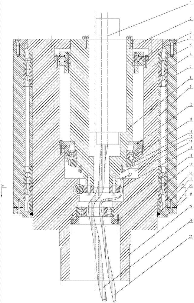
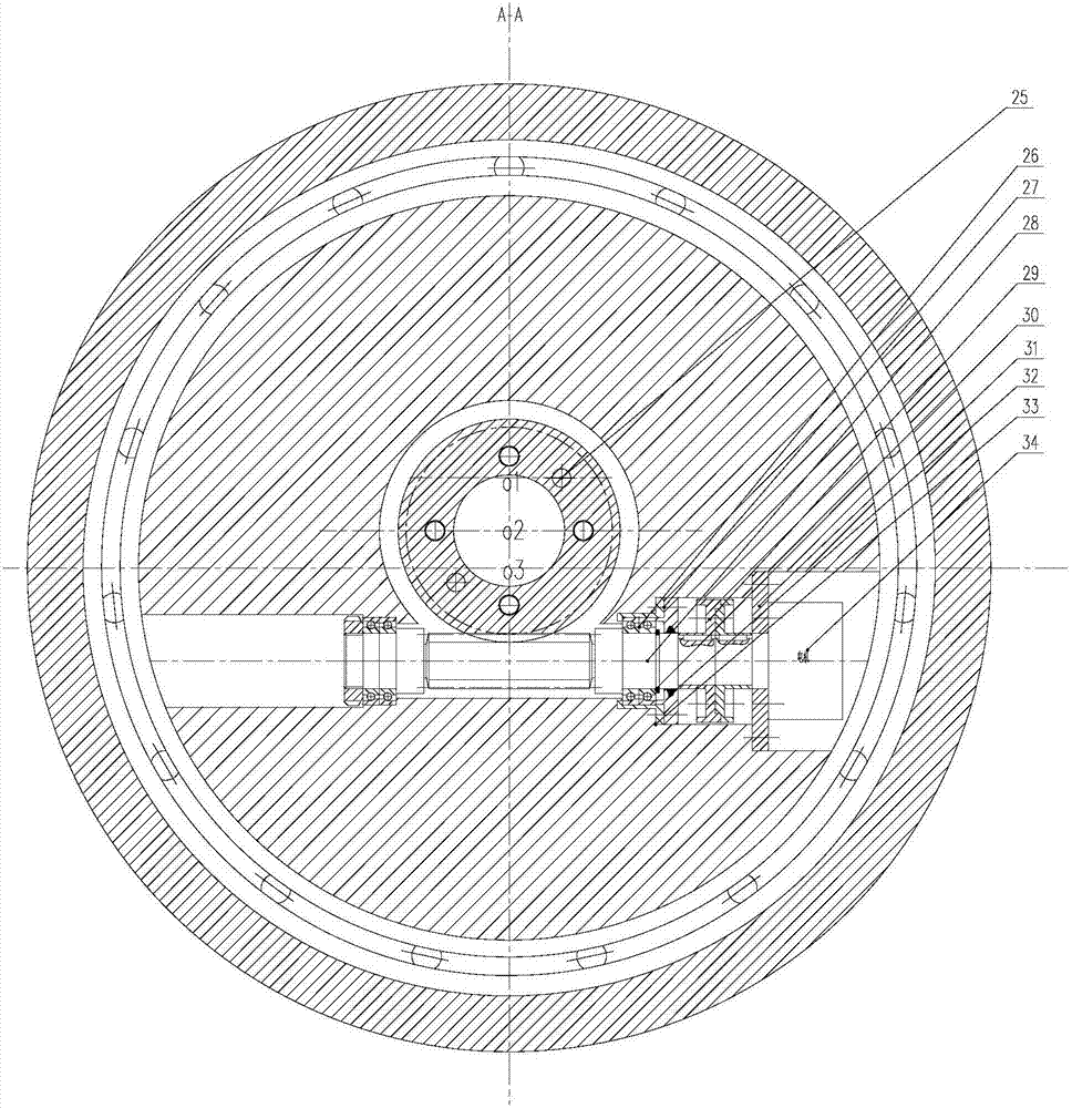
[0036] Such as figure 1 As shown, a boring, milling and grinding compound processing machine tool includes a power spindle head device. The power spindle head device includes a high-speed electric spindle 1, an electric spindle sealing end cover 2, a YRT bearing 3, a front end bearing end cover 4, a mechanical spindle 5, a front end Bearing group 6, spindle box 7, adjusting rotor shaft 8, bearing preload sleeve 9, bearing end cover 10, rotor shaft rear support bearing 11, lock nut 12, circular grating ruler 13, grating ruler reading head bracket 14, turbine 15. Grating reading head 16, lead wire bearing 17, mechanical spindle bearing lock nut 18, sealing felt ring 19, sealing gasket 20, rear end bearing cover 21, synchronous belt transmission gear 22, electric spindle power and signal line 23, Grating scale signal line 24, positioning pin 25, bearing group 26, bearing adjustment end cover sleeve cup 27, worm shaft 28, coupling 29, shaft shoulder retaining ring 30, motor connec...

Embodiment 2

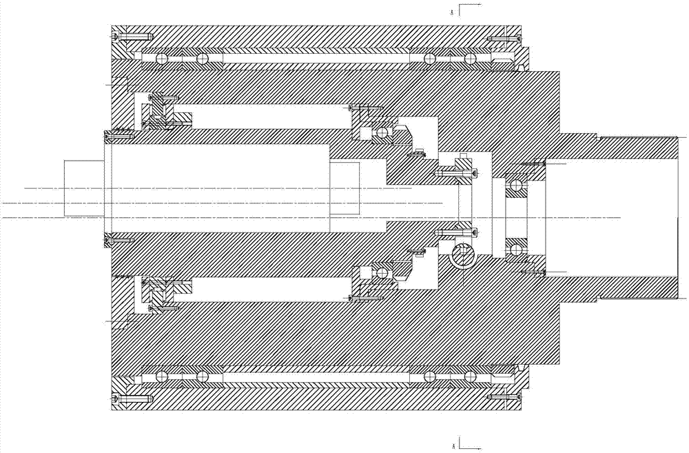
[0050] image 3 , Figure 4 The second driving method according to the present invention is shown. In the previous embodiment, the working process of the compound spindle for boring and milling combined machining has been described. The described worm-driven rotating mechanism has the disadvantages of low-speed operation and low precision. At the same time, fast linkage and radial fine-tuning of the tool cannot be completed.


PUM


Abstract

The invention discloses a boring, milling and grinding composite machining tool which comprises a power spindle head device. The power spindle head device is characterized by comprising a high-speed electric spindle, an electric spindle sealing end cover, a YRT bearing, a mechanical spindle, a front end bearing set, a spindle box, an adjusting rotor shaft, a bearing pretightening sleeve, a rotor shaft rear supporting bearing, a circular grating ruler, a grating ruler reading head support, a turbine, a grating reading head, a lead bearing, a mechanical main shaft bearing locking nut, synchronous belt transmission teeth, an electric spindle power and signal line, a grating ruler signal line, a positioning pin, a bearing set, a bearing adjusting end cover sleeve cup, a worm shaft, a coupler,a motor connection flange, an adjusting sleeve cup and a servo motor. According to the boring, milling and grinding composite machining tool, various kinds of composite machining can be achieved, theoverall size of a composite spindle is reduced through effective design, the structure is more compact and reasonable, and meanwhile the advantage of high rigidity in the radial direction and the axial direction of a composite spindle system is kept.

Description

technical field [0001] The invention relates to a compound processing machine tool, in particular to a boring, milling and grinding compound processing machine tool, which belongs to the technical field of machine tools. Background technique [0002] The hole system processing technology and processing quality of complex parts are the key factors affecting the quality of the entire part. Boring and grinding are key processes in the processing of porous parts. The advantage of the boring process is that the processed hole system has high roundness accuracy. The efficiency is low, and the quality of the processed surface is poor. These traditional processes are more difficult to process the special-shaped holes of tapered holes, tapered surfaces and other parts. Moreover, the existing machine tool equipment has low flexibility for processing hole systems, and cannot adapt to the processing of parts with different apertures. At this time, the factory needs to invest in additio...

Claims


Application Information

Patent Timeline
Patent Type & Authority Applications(China)
IPC IPC(8): B23P23/04
CPCB23P23/04
Inventor 付茂筠渠立华
Owner 徐州傲扬自动化科技有限公司
Features
  • R&D
  • Intellectual Property
  • Life Sciences
  • Materials
  • Tech Scout
  • Unparalleled Data Quality
  • Higher Quality Content
  • 60% Fewer Hallucinations
Learn More