

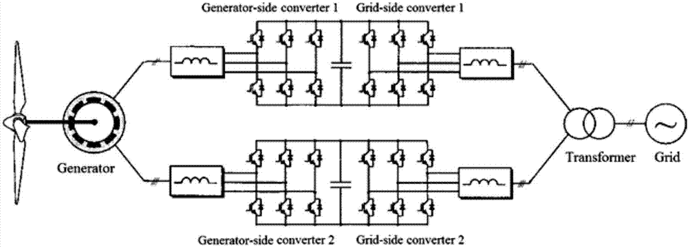
Wind power generation double winding generator system common-mode voltage suppression method
A wind turbine and common-mode voltage technology, applied in wind power generation, electrical components, circuit devices, etc., can solve problems affecting the insulation life of motor windings, system zero-sequence current loss, and motor winding insulation damage, etc., and achieve great economic value and outlook, insulation life extension, failure avoidance effects
- Summary
- Abstract
- Description
- Claims
- Application Information
AI Technical Summary
Problems solved by technology
Method used
Image

Examples
Embodiment Construction
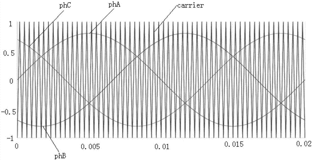
[0016] The frequency of the carrier signal defines the switching frequency of the converter, the amplitude of the carrier is a fixed value, and there is no requirement for the initial phase of the carrier. There will be no problem with PWM in a single converter. However, in a system of multiple converters, due to the interaction, the initial phase of the carrier wave in the PWM module will have a certain impact on system performance, especially for wind power systems. In the structure of multi-winding motor and converter system. Therefore, no related documents and patents can be found on how to use this effect to reduce the common-mode voltage.
[0017] The carrier frequency and phase of the grid-side converter and the machine-side converter connected to the same set of windings do not need to be the same, but the corresponding two grid-side converters and two machine-side converters connected by two sets of windings The frequency and phase need to satisfy the relationship th...
PUM
 Abstract
Description
Claims
Application Information