Stainless steel finish pipe inner wall cleaning equipment and cleaning method thereof

A technology for cleaning equipment and stainless steel, used in cleaning methods and utensils, metal processing equipment, chemical instruments and methods, etc., can solve problems such as large damage, difficult finished product quality, harsh working environment, etc., to improve cleaning efficiency and high degree of automation , the effect of reducing the operator

Pending Publication Date: 2018-05-11
宁波东鼎特种管业有限公司
View PDF4 Cites 2 Cited by
  • Summary
  • Abstract
  • Description
  • Claims
  • Application Information

AI Technical Summary

Problems solved by technology

[0003] The same industry in China adopts strong acid or strong alkali heating to clean stainless steel precision rolled tubes, which has high energy consumption, low efficiency, large corrosion and damage to the stainless steel substrate, low yield rate, difficult control of finished product quality, harsh working environment, The environmental pollution is serious, and the processing procedures and facilities for hazardous waste in the later stage are complicated and costly
Some current cleaning equipment pumps the cleaning agent from one side through the pump and flows out from the other side. The pressure at the far end is insufficient and the cleaning effect is poor, especially for the cleaning and pickling of the inner wall of the ultra-long finishing tube with a length of more than 30 meters and less than 100 meters. , it is impossible to ensure that the grease is completely removed; and the cleaning agent is directly discharged after cleaning, which is easy to cause environmental pollution, so its structure needs to be further improved

Method used


Image

  • Stainless steel finish pipe inner wall cleaning equipment and cleaning method thereof
  • Stainless steel finish pipe inner wall cleaning equipment and cleaning method thereof
  • Stainless steel finish pipe inner wall cleaning equipment and cleaning method thereof

Examples


Embodiment Construction

[0033] The present invention will be further described in detail below in conjunction with the accompanying drawings and embodiments.

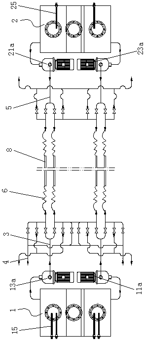
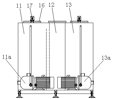
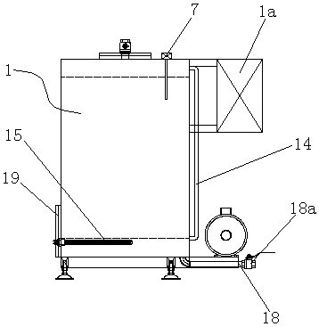
[0034] like Figure 1 to Figure 5 Shown is the structural representation of the present invention,

[0035] The reference signs are: main cleaning machine 1, main electric control box 1a, main cleaning agent tank 11, main cleaning agent pump 11a, main oil separation tank 12, main clean water tank 13, main clean water pump 13a, main liquid level sensor 14. Main heating rod 15, main inspection port 16, main breathing valve 17, main drain pipe 18, main drain valve 18a, main slag cleaning port 19, mobile cleaning machine 2, mobile terminal electric control box 2a, mobile terminal cleaning Agent tank 21, cleaning agent pump 21a at the mobile end, oil separation tank 22 at the mobile end, clean water tank 23 at the mobile end, clean water pump 23a at the mobile end, liquid level sensor 24 at the mobile end, heating rod 25 at the mobile end, mainten...


PUM


Abstract

The invention discloses stainless steel finish pipe inner wall cleaning equipment. A main control computer controls and is connected with a main electric cabinet of a main cleaning machine and a mobile terminal electric cabinet of a mobile cleaning machine, wherein a main cleaning agent groove, a main oil separation groove and a main clear water groove are formed in the main cleaning machine; a main liquid level sensor is arranged on the main cleaning machine; a main cleaning agent groove and a main clear water groove are respectively connected with a main cleaning pipe by virtue of a main cleaning agent pump and a main clear water pump; and the main cleaning pipe is connected with a scavenging pipe; a mobile terminal cleaning agent groove, a mobile terminal oil separation groove and a mobile terminal clear water groove are formed in the mobile cleaning machine; a mobile terminal liquid level sensor is arranged on the mobile cleaning machine, and the mobile terminal cleaning agent groove and the mobile terminal clear water groove are respectively connected with a mobile terminal cleaning pipe by virtue of a mobile terminal cleaning agent pump and a mobile terminal clear water pump;and quick flexible pipes are arranged on a main cleaning pipe and a mobile terminal cleaning pipe, and the main cleaning agent groove and the mobile terminal cleaning agent groove respectively contain a water-based type environment-friendly cleaning agent. A cleaning method of the equipment comprises the following steps: cleaning with the cleaning agent, washing, and carrying out purging and airdrying. The equipment disclosed by the invention has the advantages of simple structure, high cleaning efficiency and good quality.

Description

technical field [0001] The invention relates to the technical field of industrial cleaning, in particular to the internal cleaning of ultra-long (length greater than 30 meters and less than 100 meters) stainless steel finish-rolled pipes, in particular to a cleaning device for the inner wall of stainless steel finish-rolled pipes and a cleaning method thereof. Background technique [0002] The elongation of ultra-long (30m≤L≤100m) stainless steel finish rolling tube is about 2.39~3.39 times during rolling, and the rolled product will inevitably produce stress, lattice shift and grain deformation, which will cause carbon segregation, and also cause carbon segregation. It will produce cold work hardening to increase the hardness and produce deformed martensite. To solve the above problems, it is necessary to carry out bright solution treatment on the rolled pipe. During the rolling process, the inner wall is automatically supplied with internal lubricating rolling oil through ...

Claims


Application Information

Patent Timeline
Patent Type & Authority Applications(China)
IPC IPC(8): B08B9/032B21B45/02
CPCB08B9/032B21B45/0269B21B45/0275
Inventor 吴通良何永红周耀
Owner 宁波东鼎特种管业有限公司
Why Eureka
Try Eureka