Active and passive coordinated regulated magnetic levitation wind yawing system

A yaw system and magnetic levitation technology, applied in engine control, wind engine, engine control parameters and other directions, can solve the problems of large yaw power consumption of wind turbines, the suspension air gap is easily affected by external interference, and the suspension power consumption is increased. Achieve the effect of reducing equipment cost and equipment failure rate, reducing yaw power consumption and suspension power consumption, and improving suspension stiffness and stability

Active Publication Date: 2018-05-11
QUFU NORMAL UNIV
View PDF7 Cites 14 Cited by
  • Summary
  • Abstract
  • Description
  • Claims
  • Application Information

AI Technical Summary

Problems solved by technology

The traditional wind power yaw system generally adopts multi-motor multi-gear coupling technology, which has problems such as complex structure, high failure rate, and poor anti-interference ability. , which seriously affects the stability of the system. Invention patents 200910161406.7 and 201410143297.7 respectively disclose two kinds of magnetic levitation wind yaw systems, which realize the yaw windward and crosswind protection under the stable suspension of the cabin, and greatly reduce the yaw power consumption. However, the magnetic levitation The nature of the system is non-linear, weakly damped and unstable, especially the wind-driven yaw system, which generally operates on a tower with a height of 80 meters. The wind speed fluctuates randomly, which can easily cause suspension vibration or instability. Active suspension control is to ensure The stable suspension of the wind turbine nacelle is the key, bu

Method used


Image

  • Active and passive coordinated regulated magnetic levitation wind yawing system
  • Active and passive coordinated regulated magnetic levitation wind yawing system
  • Active and passive coordinated regulated magnetic levitation wind yawing system

Examples


Embodiment Construction

[0017] The present invention will be further described below in conjunction with the accompanying drawings and embodiments.

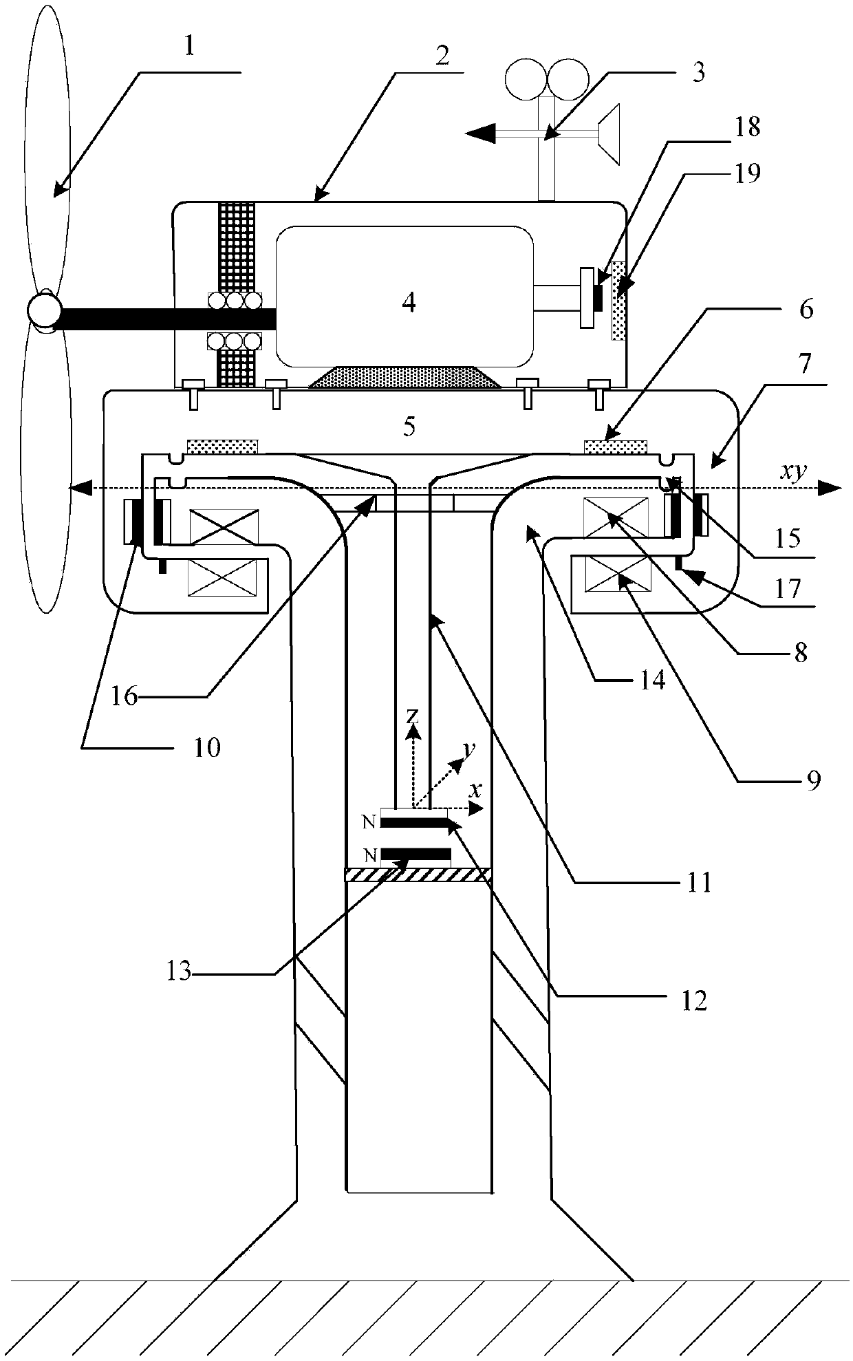
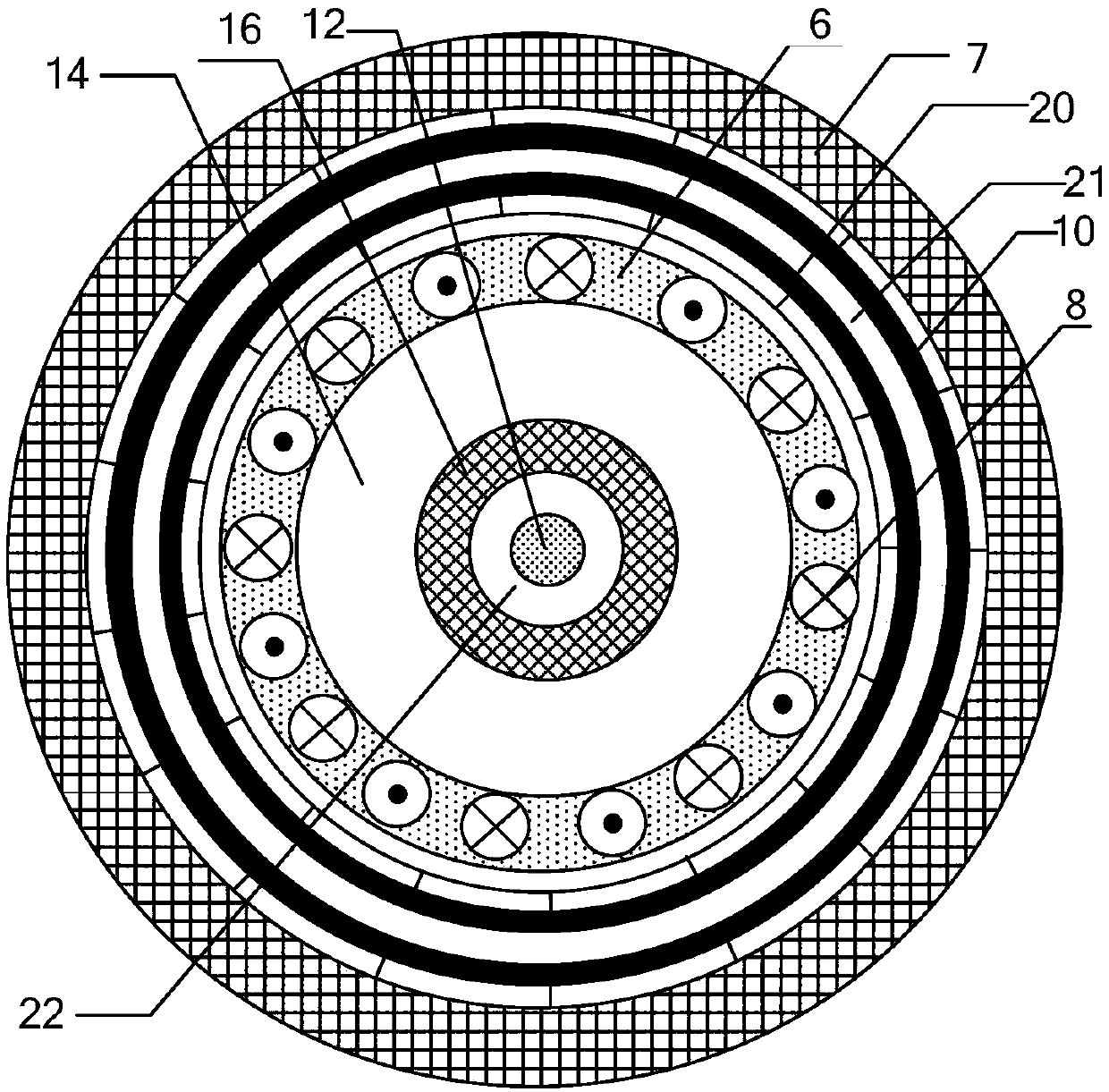
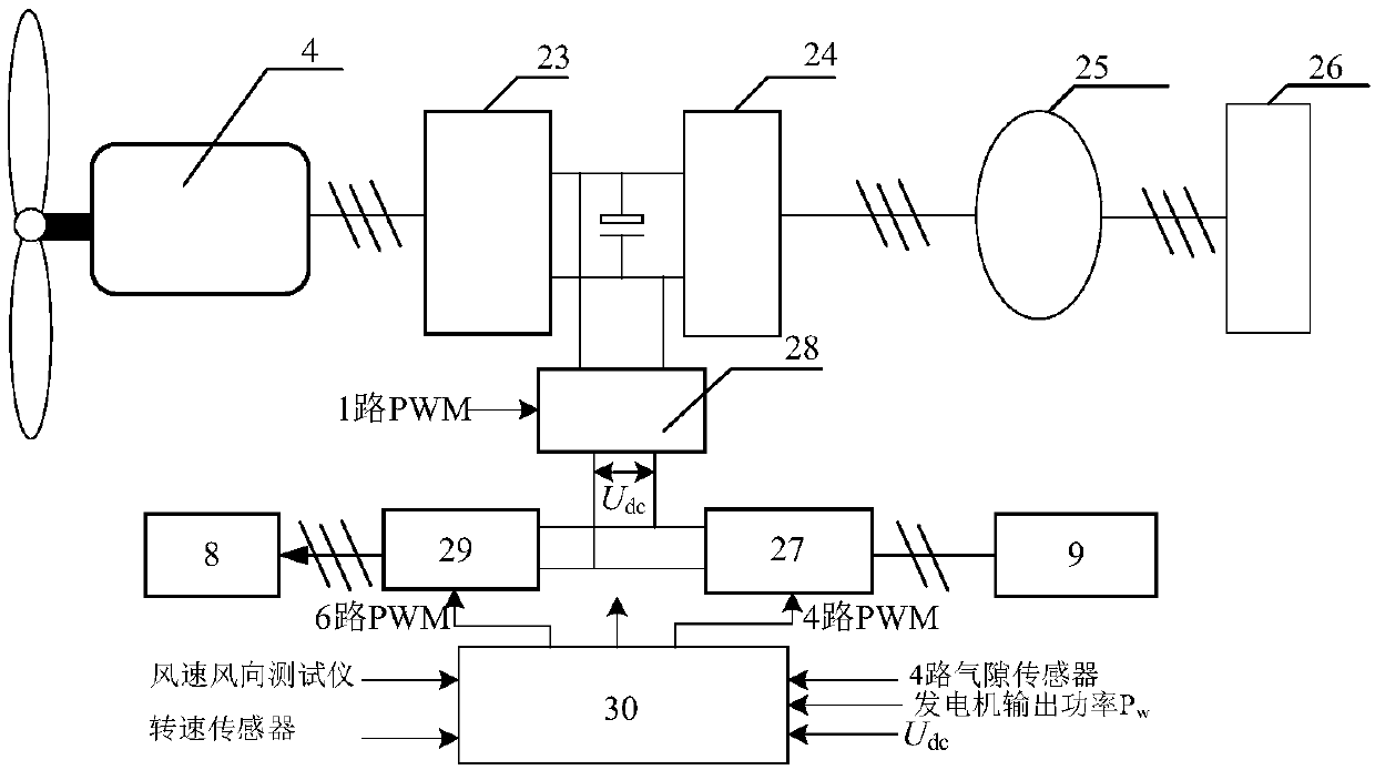
[0018] The active-passive coordinated control maglev wind yaw system disclosed in the present invention includes a nacelle 2 , a yaw support body 7 , a pitch adjustment suspension 11 and a suspension tower 14 . Wherein the nacelle includes a blade 1, a generator 4, an anemometer 3, a shock-absorbing tail shaft 18, a shock-absorbing aluminum plate 19, and a nacelle base 5, an annular aluminum plate 6, a yaw winding 9, and a yaw support body 7 are installed. The vertical permanent magnet 10 of the yaw support body, the suspension tower 14 includes the suspension winding 8, the vertical permanent magnet 20 of the suspension tower, and the inner support of the tower. The converter 28 is completed under the action of the DSP28035 main control unit 30 , and the active yaw is completed by the yaw winding 9 , the three-phase inverter 29 and the BUCK converter 2...


PUM


Abstract

The invention discloses an active and passive coordinated regulated magnetic levitation wind yawing system applied to large- and medium-sized wind turbine generators. The system comprises a cabin, a yawing supporting body, a pitch adjusting suspension rack and a suspension tower to finish enhancement of pitch rigidity of the yawing supporting body, high frequency air gap fluctuation inhibition, horizontal displacement passive adjustment, active suspension control and cabin yawing control in a coordinated manner; a 6mm thick aluminum plate is arranged in a cabin base of the yawing supporting body to generate an eddy-current damping force to passively inhibit high frequency fluctuation of an axial suspension air gap. The pitch rigidity of the cabin is enhanced by means of the pitch adjustingsuspension rack, permanent magnets and a suspension tower-based support, and the active suspension degree of freedom, the horizontal repulsive force between the permanent magnet on the inner side ofthe yawing supporting body and the permanent magnet on the outer side of the suspension tower and the passive balanced water level displacement are reduced; windward and crosswind protection of passive yawing when the cabin is suspended stably is achieved under control of a master control unit DSP28035 of a BUCK converter, an H bridge converter and a three phase inverter by active suspension and yawing separately.

Description

technical field [0001] The invention relates to a fan yaw system of a large and medium-sized wind turbine, through active and passive coordinated regulation to realize yaw facing windward and sidewind protection under nacelle suspension, especially a wind-forced magnetic levitation that can reduce the degree of freedom of active suspension control and suspension power consumption Yaw system. Background technique [0002] With the aggravation of environmental pollution and energy crisis, wind power generation has attracted the attention of countries all over the world because of its complete non-pollution. Wind yaw systems are key components of large horizontal-axis wind power systems, enhancing maximum capture of wind energy and protection from crosswinds. The traditional wind power yaw system generally adopts multi-motor multi-gear coupling technology, which has problems such as complex structure, high failure rate, and poor anti-interference ability. , which seriously af...

Claims


Application Information

Patent Timeline
IPC IPC(8): F03D7/02F03D7/04
CPCF03D7/0204F03D7/047F05B2270/32F05B2270/304F05B2270/321F05B2270/602Y02E10/72
Inventor 褚晓广蔡彬孔英王强衣学涛李向东
Owner QUFU NORMAL UNIV
Why Eureka
Try Eureka