
Bearing automatic cleaning and drying device

A drying device and automatic cleaning technology, which is applied in the direction of drying, drying machine, heating device, etc., can solve the problems of uneven heating, high labor intensity, damage to the washing machine, etc., and achieve faster air circulation speed and high degree of automation , the effect of preventing annealing and deterioration

Pending Publication Date: 2018-05-18
XINCHANG WEIERTE BEARING
View PDF0 Cites 5 Cited by
  • Summary
  • Abstract
  • Description
  • Claims
  • Application Information

AI Technical Summary

Problems solved by technology

[0003] In actual production operation, it is found that the reason why the bearing does not turn is that the greasy and fluff are dried and solidified by high temperature. The bearing itself has basically no wear or wear is very small. The bearing needs to be cleaned. Kerosene is usually used for cleaning the bearing. cleaning agent manually, because kerosene has a strong smell, which is harmful to human health, pollutes the environment, labor intensity is high, and labor cost is high. Moreover, the bearing cleaning machines currently on the market are not only complex in structure, but the centrifugal force generated by high-speed rotation during the cleaning process is easy. The bearing is thrown out, which is easy to cause damage to the washing machine itself, and there is a big safety hazard when using it
After the bearing is cleaned, blower and other components are usually used to dry the surface of the bearing, but this drying method is unevenly heated, which may easily cause excessive local temperature to damage the bearing, low efficiency, high cost, and the machine occupies a large area

Method used


Image

  • Bearing automatic cleaning and drying device
  • Bearing automatic cleaning and drying device

Examples


Embodiment Construction

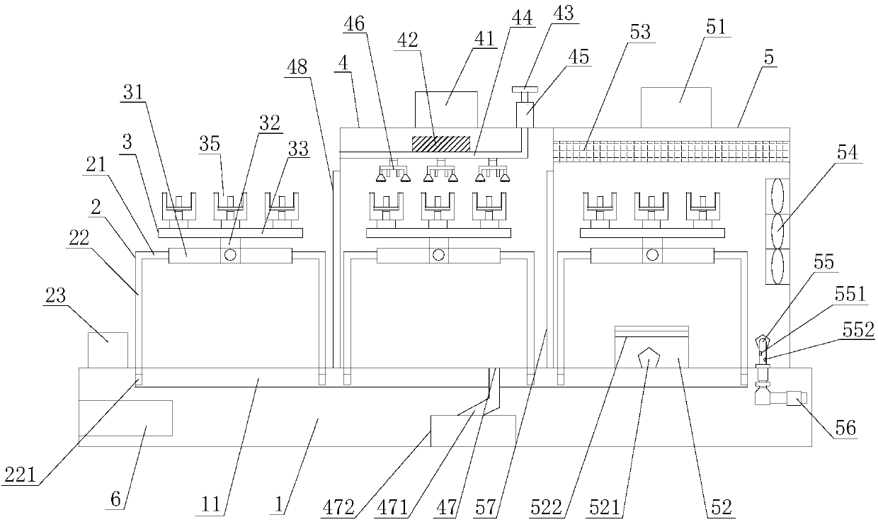
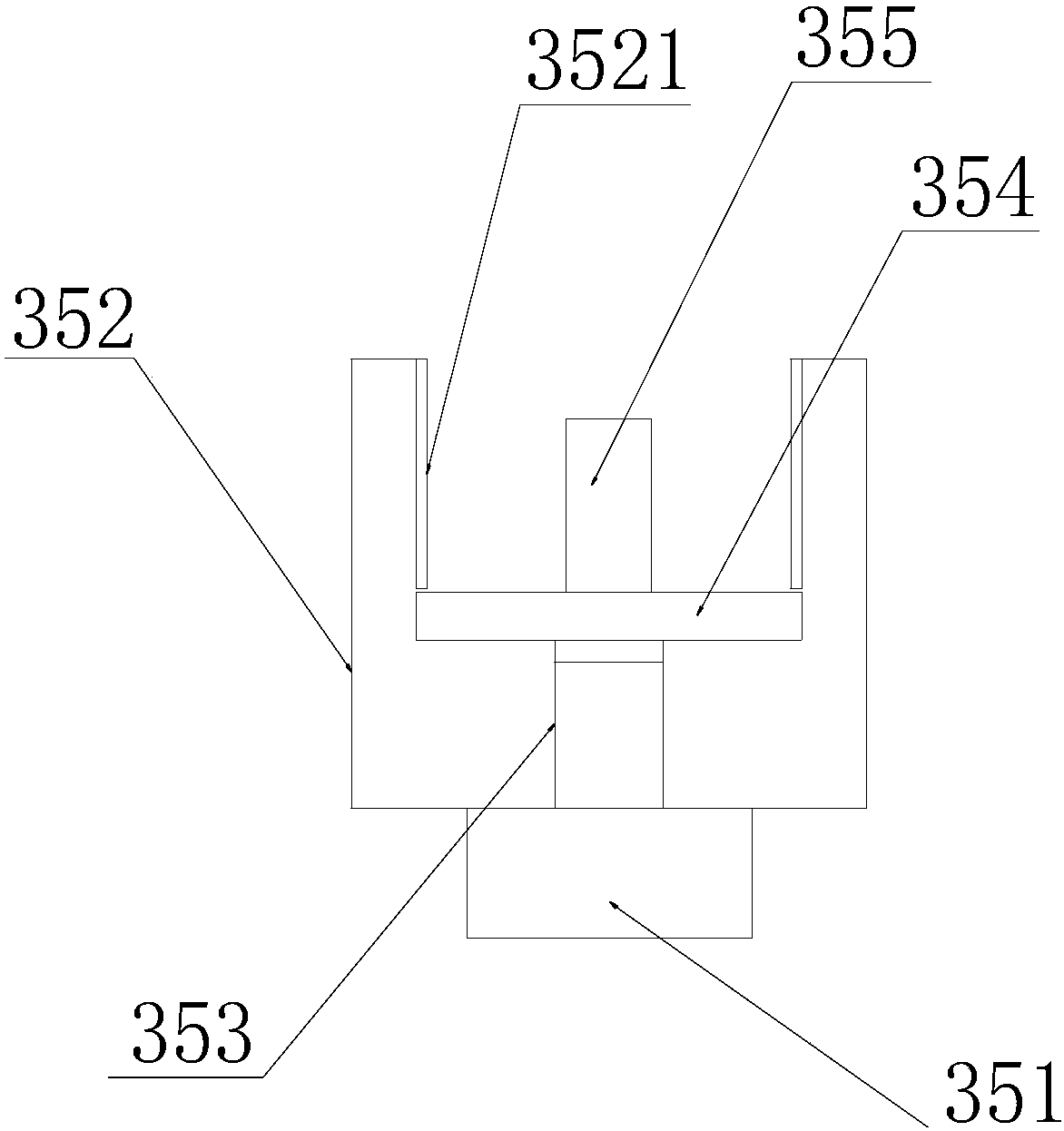
[0015] refer to figure 1 and figure 2 , a bearing automatic cleaning and drying device of the present invention, comprising a base 1, a mobile work frame 2, a bearing placement frame 3, a cleaning mechanism 4, a drying mechanism 5 and a control mechanism 6, the cleaning mechanism 4, the drying mechanism 5 Installed and fixed on the base 1, the cleaning mechanism 4 is connected with the drying mechanism 5, the cleaning mechanism 4 is provided with the first first door 48 driven by the control mechanism 6, and the drying mechanism 5 is provided with The second warehouse door 57 driven by the control mechanism 6, the mobile work frame 2 is compatible with the first first warehouse door 48 and the second warehouse door 57, and the mobile work frame 2 is movably installed on the base 1 , the bearing mounting frame 3 is installed and fixed on the mobile work frame 2, and the bearing mounting frame 3 is provided with several bearing fixing seats 35, and the cleaning mechanism 4 inc...


PUM


Abstract

The invention discloses a bearing automatic cleaning and drying device which comprises a base, a movable workbench, a bearing storing frame, a cleaning mechanism, a drying mechanism and a control mechanism. The cleaning mechanism comprises a first driving motor, an ultrasonic generator, a water inlet, a water inlet pipe, a booster pump and a high-pressure spraying head. The drying mechanism comprises a second driving motor, an air bellow, a resistance wire heating plate, an air discharging opening, an air guiding pipeline and an air discharging pipe. A fan is arranged in the air bellow. According to the bearing automatic cleaning and drying device, through mutual cooperation of the ultrasonic generator, the booster pump and the high-pressure spraying head, stains of all dead corners of a bearing are removed, and the cleaning effect is good; through mutual cooperation of the air bellow, the resistance wire heating plate, the air discharging opening, the air guiding pipeline and the airdischarging pipe, the air circulating speed is increased, and the quick drying effect is achieved through ventilating and heating; and the humidity and the temperature of the drying mechanism are monitored in real time through a humidity sensor and a temperature sensor, the drying time is controlled, and the situation that due to the too high temperature, the bearing is subjected to annealing metamorphism is prevented.

Description

【Technical field】 [0001] The invention relates to the technical field of bearing auxiliary equipment, in particular to the technical field of an automatic bearing cleaning and drying device. 【Background technique】 [0002] Bearing is an important basic component of various mechanical equipment, its precision, performance, life and reliability play a decisive role in the accuracy, performance, life and reliability of the main engine. Among mechanical products, bearings are high-precision products, which not only require the comprehensive support of mathematics, physics and many other disciplines, but also require material science, heat treatment technology, precision machining and measurement technology, numerical control technology and effective numerical methods and powerful computers. Technology and many other disciplines serve it. Therefore, bearings are also a product that represents the country's scientific and technological strength. After the outbreak of the internat...

Claims


Application Information

Patent Timeline
Patent Type & Authority Applications(China)
IPC IPC(8): B08B3/12B08B3/02F26B21/00F26B23/06F26B21/08F26B21/10
CPCB08B3/123B08B3/022F26B21/00F26B21/08F26B21/10F26B23/06
Inventor 单秀英
Owner XINCHANG WEIERTE BEARING
Learn More