Method and device for coal direction liquefaction

A technology of direct coal liquefaction and coal liquefaction, applied in the field of coal chemical industry, can solve the problems of poor oil yield, high gas yield, and low liquefaction conversion rate, so as to improve oil yield, increase hydrogen partial pressure, and reduce residence time Effect

Active Publication Date: 2018-05-18
CHNA ENERGY INVESTMENT CORP LTD +2
View PDF6 Cites 6 Cited by
  • Summary
  • Abstract
  • Description
  • Claims
  • Application Information

AI Technical Summary

Problems solved by technology

[0005] The main purpose of the present invention is to provide a direct coal liquefaction method and a coal direct liquefaction device to solve the problem of low liquefaction conversion rate and high gas yield in the prior art direct coal liquefaction method, resulting in poor oil yield.

Method used


Image

  • Method and device for coal direction liquefaction
  • Method and device for coal direction liquefaction
  • Method and device for coal direction liquefaction

Examples


preparation example Construction

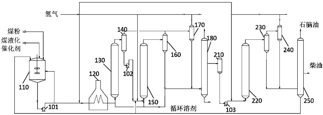
[0047] In the preparation method provided by the present invention, the liquefaction reaction can adopt the reactor commonly used by those skilled in the art. In a preferred embodiment, the first liquefaction reactor 130 and the second liquefaction reactor 150 are independently selected from a forced circulation suspended bed reactor, a bubbling bed reactor, a slurry bed reactor or a reactor with a draft tube The loop reactor, more preferably a forced circulation suspended bed reactor, can ensure the liquid flow rate in the coal liquefaction reactor, reduce the deposition of solids, and realize the long-term stable operation of the device.

[0048] According to the above teaching of the present invention, those skilled in the art can select a specific operating system for directly liquefying coal to prepare liquid fuel. The specific operation process can be as follows:

[0049] The coal is crushed and turned into coal powder, which is dried and mixed with circulating solvent ...
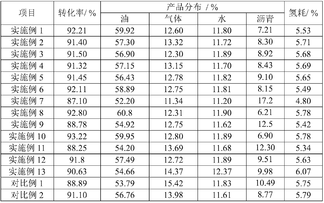
Embodiment 1

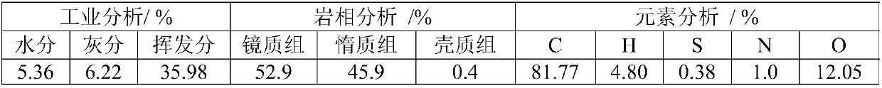
[0054] The coal direct liquefaction method provided in this example adopts the coal direct liquefaction continuous test device to carry out the coal liquefaction test. The device adopts two suspended bed reactors with forced circulation, and an intermediate separator is arranged between the reactors. After separation, the liquid and solid phase materials are partly recycled back to the inlet of the first liquefaction reactor. Using Shendong coal as the test raw material coal, the raw material coal, catalyst, and coal liquefaction circulating solvent were mixed in a coal slurry tank to obtain a coal slurry. The basic properties of the raw material coal are shown in Table 1. The above-mentioned direct coal liquefaction method includes the following steps:

[0055] First, the above-mentioned coal slurry and hydrogen enter the first liquefaction reactor (forced circulation suspended bed reactor), and the first liquefied product at the outlet of the first liquefaction reactor enters...

Embodiment 2

[0058] The difference between the direct coal liquefaction method provided in this example and Example 1 is:

[0059] The feed ratio of part of the second liquid phase product to the first raw material is 0.1.


PUM

PropertyMeasurementUnit
densityaaaaaaaaaa
densityaaaaaaaaaa

Abstract

The invention provides a method and device for coal direction liquefaction. The method for the coal direct liquefaction includes the following steps of: S1, performing a first liquefaction reaction ona first raw material which includes coal slurry and hydrogen so as to obtain first liquefied products, and performing oil-gas separation on the first liquefied products to obtain a first liquid-phaseproduct; S2, performing a second liquefaction reaction on a second raw material which comprises the first liquid-phase product, hydrogen and a solvent so as to obtain second liquefied products, and performing oil-gas separation on the second liquefied products to obtain a second liquid-phase product; S3, performing distillation and catalytic hydrogenation treatment on a part of the second liquid-phase product so as to obtain a coal liquefaction product; and S4, performing the steps of S1-S3 repeatedly, wherein the first raw materials and / or the second raw materials also include the rest of the second liquid-phase product during the repeated operation. Through the method for the coal direct liquefaction, the liquefaction conversion rate and liquid product yield of coal can be improved, andthe resource utilization rate can be improved significantly.

Description

technical field [0001] The invention relates to the field of coal chemical industry, in particular to a coal direct liquefaction method and a coal direct liquefaction device. Background technique [0002] Coal direct liquefaction technology refers to the process of direct conversion of coal to liquid products and a small amount of gas products through hydrogenation under the action of high temperature, high pressure, hydrogen, solvent and catalyst. The process of direct coal liquefaction usually includes four main parts: oil-coal slurry preparation, coal hydroliquefaction reaction, solid-liquid separation, and product upgrading, processing and utilization. Coal is crushed, dried, and ground into coal powder, and is prepared together with solvent and catalyst to make oil-coal slurry suitable for transportation and heat transfer. After boosting and preheating, the oil-coal slurry is transported to the coal hydrogenation liquefaction reactor. The lower coal undergoes pyrolysis...

Claims


Application Information

Patent Timeline
Patent Type & Authority Applications(China)
IPC IPC(8): C10G1/00
CPCC10G1/006C10G2300/70C10G2400/04
Inventor 高山松舒歌平李克健杨葛灵章序文李永伦王洪学姜元博王国栋杨玉峰
Owner CHNA ENERGY INVESTMENT CORP LTD
Why Eureka
Try Eureka