Method for two-stage catalytic direct liquefaction of coal and application thereof

A direct and catalytic technology, applied in the preparation of liquid hydrocarbon mixtures, bulk chemical production, petroleum industry, etc., can solve the problems of insufficient coal conversion rate and oil yield

Active Publication Date: 2020-11-03
CHINA SHENHUA COAL TO LIQUID & CHEM CO LTD +1
View PDF13 Cites 1 Cited by
  • Summary
  • Abstract
  • Description
  • Claims
  • Application Information

AI Technical Summary

Problems solved by technology

[0005] The purpose of the present invention is to provide a method for direct liquefaction of coal with two-stage catalysis in order to overcome the problems of insufficient coal conversion rate

Method used


Image

  • Method for two-stage catalytic direct liquefaction of coal and application thereof
  • Method for two-stage catalytic direct liquefaction of coal and application thereof
  • Method for two-stage catalytic direct liquefaction of coal and application thereof

Examples


Embodiment 1

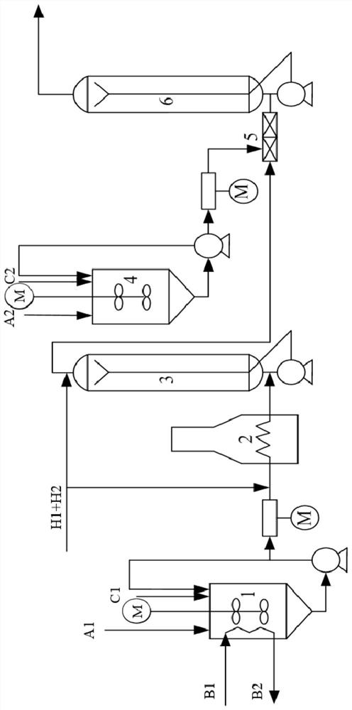
[0111] 1) Stir the first catalyst C1, sulfur powder, coal powder and hydrogen-donating solvent A1 in the coal slurry preparation tank 1, and mix uniformly to prepare a coal slurry, wherein the concentration of the coal slurry is 45% by weight, calculated as iron element , the amount of the first catalyst used is 0.8% by weight of the coal powder, and the molar ratio of the first catalyst in terms of iron element to the sulfur powder in terms of sulfur element is 1:1.5. After mixing evenly, it is preheated to 395°C by the coal slurry preheater 2, and then sent to the first-stage reactor bubbling bed reactor 3 for a stage of liquefaction reaction. 19MPa;

[0112] 2) Homogenously mix the second catalyst C2 with the hydrogen-donating solvent A2 in the catalyst oil slurry homogenization tank 4, and then mix it with the first-stage liquefaction reaction product obtained in step 1) under the action of the static mixer 5, and then introduce the mixture into The second-stage reactor b...

Embodiment 2

[0114] 1) Stir the first catalyst C1, sulfur powder, coal powder and hydrogen-donating solvent A1 in the coal slurry preparation tank 1, and mix uniformly to prepare a coal slurry, wherein the concentration of the coal slurry is 40% by weight, calculated as iron element , the amount of the first catalyst is 0.5% by weight of the coal powder, and the molar ratio of the first catalyst in terms of iron element to the sulfur powder in terms of sulfur element is 1:2.5. After mixing evenly, it is preheated to 385°C by the coal slurry preheater 2, and then sent to the first-stage reactor bubbling bed reactor 3 for a first-stage liquefaction reaction. The temperature of the first-stage liquefaction reaction is 440°C, the time is 30 minutes, and the hydrogen pressure is 20MPa;

[0115] 2) Homogenously mix the second catalyst C2 with the hydrogen-donating solvent A2 in the catalyst oil slurry homogenization tank 4, and then mix it with the first-stage liquefaction reaction product obtai...

Embodiment 3

[0117] 1) Stir the first catalyst C1, sulfur powder, coal powder and hydrogen-donating solvent A1 in the coal slurry preparation tank 1, and mix uniformly to prepare a coal slurry, wherein the concentration of the coal slurry is 50% by weight, calculated as iron element , the amount of the first catalyst is 1.2% by weight of the coal powder, and the molar ratio of the first catalyst in terms of iron element to the sulfur powder in terms of sulfur element is 1:2. After mixing evenly, it is preheated to 399°C by the coal slurry preheater 2, and then sent to the first-stage reactor bubbling bed reactor 3 for a stage of liquefaction reaction. 19MPa;

[0118] 2) Homogenously mix the second catalyst C2 with the hydrogen-donating solvent A2 in the catalyst oil slurry homogenization tank 4, and then mix it with the first-stage liquefaction reaction product obtained in step 1) under the action of the static mixer 5, and then introduce the mixture into Two-stage reactor The two-stage l...


PUM


Abstract

The invention relates to the field of direct coal liquefaction, and discloses a two-stage catalytic direct coal liquefaction method and application thereof. The method comprises the following steps: 1) carrying out a first-stage liquefaction reaction on coal slurry containing a first catalyst, a sulfur auxiliary agent, pulverized coal and a hydrogen-donating solvent and hydrogen; and 2) in the presence of a second catalyst, the product obtained in the step 1) and hydrogen are subjected to a two-stage liquefaction reaction, wherein the first catalyst is an iron-based catalyst, and the active component of the second catalyst is selected from one or more of cobalt, molybdenum, nickel, tungsten and iron. By adopting the method to directly liquefy the coal, the coal conversion rate, the oil yield and the liquefaction hydrogen supply performance of the liquefied crude oil can be improved.

Description

technical field [0001] The invention relates to the field of direct coal liquefaction, in particular to a two-stage catalytic direct liquefaction method for coal and its application. Background technique [0002] Coal direct liquefaction is a new type of coal chemical clean coal technology that converts coal into liquid products under the condition of high temperature and high pressure in the presence of hydrogen, under the dual action of hydrogen-donating solvent and catalyst, thermochemical reaction and catalytic reaction occur. The coal direct liquefaction oil produced by this technology has high density, high heat capacity, high thermal stability, high calorific value, low freezing point, low sulfur, low nitrogen, low aromatics, and high naphthenes, which are different from conventional petroleum-based oils. Unique physical properties can provide a new source of military oil and special fuel in the aerospace field. In addition, the pitch obtained from coal liquefaction ...

Claims


Application Information

Patent Timeline
IPC IPC(8): C10G1/06C10G1/08
CPCC10G1/083C10G1/065C10G1/086Y02P20/52
Inventor 王洪学谢晶李导舒歌平杨葛灵单贤根吴剑平
Owner CHINA SHENHUA COAL TO LIQUID & CHEM CO LTD
Why Eureka
Try Eureka