
Scanning laser interference type fiber optic acoustic phase-locked detection system and scanning laser interference type fiber optic acoustic phase-locked detection method

A technology for scanning lasers and detection systems, applied in the measurement of color/spectral characteristics, etc., can solve the problems of low accuracy and poor stability of photoacoustic signal demodulation, and achieve the effect of improving accuracy and limit sensitivity

Active Publication Date: 2018-05-18
DALIAN UNIV OF TECH
View PDF3 Cites 15 Cited by
  • Summary
  • Abstract
  • Description
  • Claims
  • Application Information

AI Technical Summary

Problems solved by technology

[0004] The object of the present invention is to propose a scanning laser interference optical fiber acoustic wave phase-locked detection system and method for photoacoustic spectroscopy, aiming to solve the photoacoustic problems existing in the all-optical photoacoustic spectrometer based on fiber optic Fabry-Perot microphones. Poor signal demodulation stability and low precision, etc., further improve the detection sensitivity of trace gas detection, and expand a larger space for the application of photoacoustic spectroscopy in trace gas detection

Method used


Image

  • Scanning laser interference type fiber optic acoustic phase-locked detection system and scanning laser interference type fiber optic acoustic phase-locked detection method
  • Scanning laser interference type fiber optic acoustic phase-locked detection system and scanning laser interference type fiber optic acoustic phase-locked detection method
  • Scanning laser interference type fiber optic acoustic phase-locked detection system and scanning laser interference type fiber optic acoustic phase-locked detection method

Examples


Embodiment Construction

[0029] The specific embodiments of the present invention will be described in detail below in conjunction with the technical solution and the drawings.

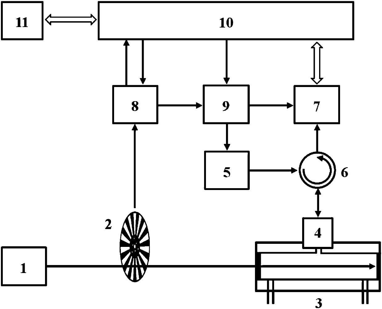
[0030] The system structure diagram of the present invention is as figure 1 As shown, it mainly includes photoacoustic excitation light source 1, light modulator 2, photoacoustic cell 3, fiber microphone 4, broadband scanning laser light source 5, fiber circulator 6, high-speed wavelength query module 7, phase locked loop 8, square wave signal Generator 9, digital signal processor 10 and computer 11.

[0031] The photoacoustic excitation light source 1 undergoes light intensity modulation by the light modulator 2, and then enters the photoacoustic cell 3; after the gas molecules in the photoacoustic cell 3 absorb light energy, the heat generated by the non-radiative transition causes the gas to move periodically And form a sound wave; sound pressure acts on the surface of the diaphragm of the optical fiber microphone 4, causing th...


PUM


Abstract

The invention provides a scanning laser interference type fiber optic acoustic phase-locked detection system and a scanning laser interference type fiber optic acoustic phase-locked detection method,which belong to the technical field of trace gas detection. The system comprises a photoacoustic excitation light source, a light modulator, a photoacoustic cell, a fiber optic microphone, a broad-band scanning laser source, a fiber optic circulator, a high-speed wavelength query module, a phase-locked loop, a square-wave signal generator, a digital signal processor, and a computer. By carrying out synchronous wavelength scanning control and synchronous spectrum sampling control on the broad-band scanning laser source and the high-speed wavelength query module and combining the Fabry-Perot cavity length high-speed synchronous demodulation technique based on a fiber optic scanning laser interferometer with the phase-locked amplification technique, the invention realizes high sensitivity andhighly stable detection on weak photoacoustic signals. The invention can greatly increase the precision and limit sensitivity of photoacoustic spectrometry-based trace gas detection, and provides a highly competitive technical solution for photoacoustic spectrometry-based trace gas detection.

Description

Technical field [0001] The invention belongs to the technical field of trace gas detection, and relates to a scanning laser interference type optical fiber acoustic wave phase-locked detection system and method. Background technique [0002] Photoacoustic spectroscopy trace gas detection technology has significant advantages such as high sensitivity and small sampling volume. It has shown wide applications in the fields of environmental pollution gas monitoring, dissolved gas analysis in transformer oil, and coal mine flammable and explosive gas monitoring. prospect. [0003] In the photoacoustic spectroscopy measurement, the gas molecules in the gas cell absorb light energy and undergo a non-radiative transition to produce a heat change, which causes the gas to vibrate and generate sound waves. For the detection of very low concentrations of trace gases, the photoacoustic signal is usually only in the micropascal level. According to the principle of photoacoustic spectroscopy, t...

Claims


Application Information

Patent Timeline
IPC IPC(8): G01N21/39
CPCG01N21/39
Inventor 陈珂于清旭
Owner DALIAN UNIV OF TECH
Learn More