
Pure nitrogen preparation device and process

A pure nitrogen and liquid nitrogen technology, used in refrigeration and liquefaction, lighting and heating equipment, liquefaction and other directions, can solve the problems of low extraction rate of the device, high unit consumption of products, not suitable for large-scale nitrogen consumption, etc. efficiency, large cooling capacity, and the effect of saving electricity

Pending Publication Date: 2018-05-22
HANGZHOU TURNING ENERGY TECH DEV CO LTD
View PDF6 Cites 9 Cited by
  • Summary
  • Abstract
  • Description
  • Claims
  • Application Information

AI Technical Summary

Problems solved by technology

[0003] The commonly used pure nitrogen equipment on the market is divided into two types: single-tower nitrogen production and double-tower nitrogen production. The single-tower nitrogen production is smooth and can produce a certain pressure of product nitrogen for direct use by users. Although this type of process is simple in structure, However, the extraction rate of the device is low, and the unit consumption of the product is high, which is not suitable for the large-scale use of nitrogen; the double-tower nitrogen production can produce nitrogen at atmospheric pressure or low-pressure nitrogen with a pressure of 0.1-0.2MpaG, and the extraction rate of the device is high. Energy consumption It is lower than single tower nitrogen production, but due to the lower product pressure, the product nitrogen needs to be compressed by a nitrogen compressor to meet the user's requirements for nitrogen pressure

Method used


Image

  • Pure nitrogen preparation device and process
  • Pure nitrogen preparation device and process

Examples


Embodiment Construction

[0033] The present invention will be further explained below in conjunction with the embodiments and the accompanying drawings. The following examples are only used to illustrate the present invention, but are not intended to limit the scope of the present invention.

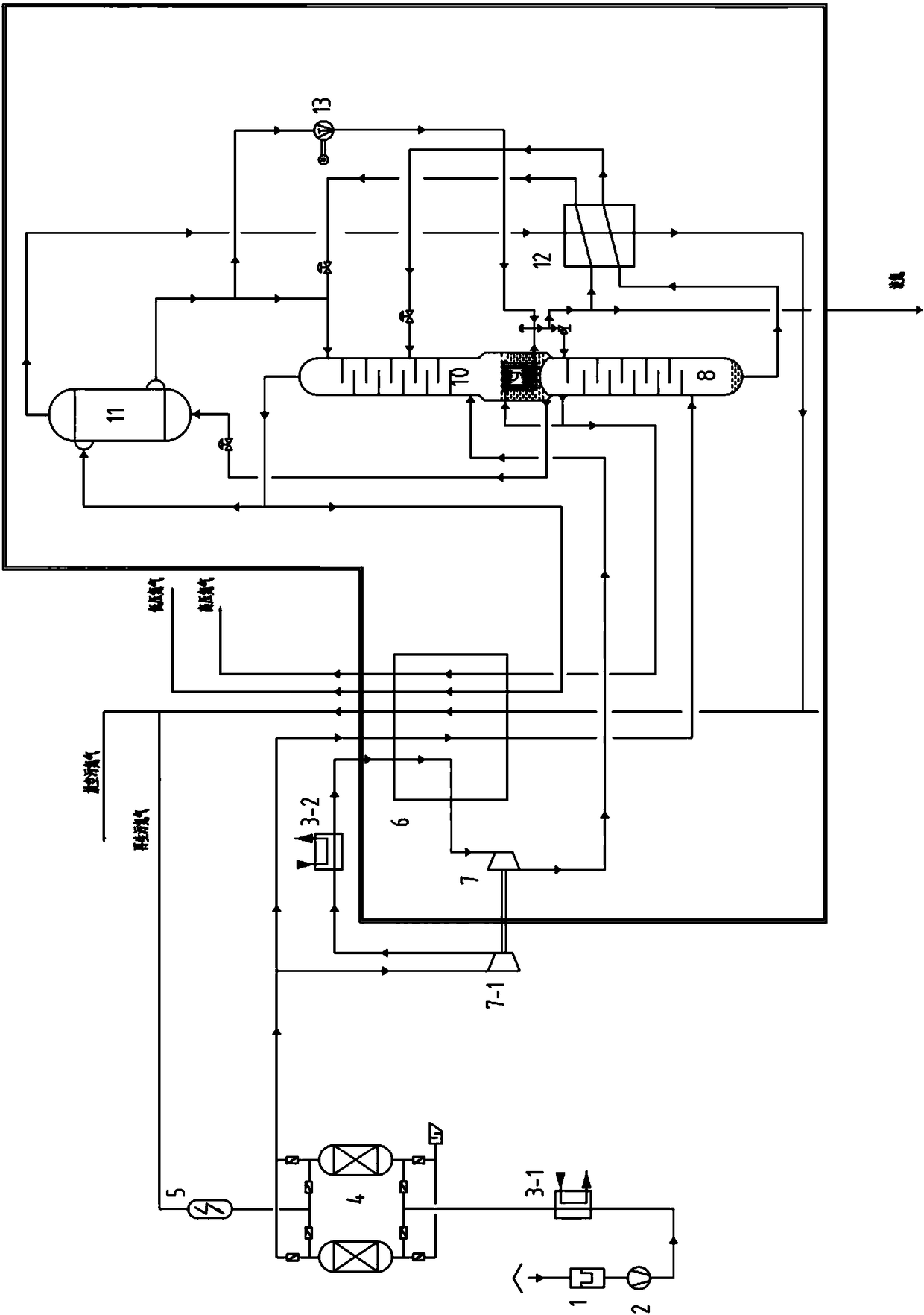
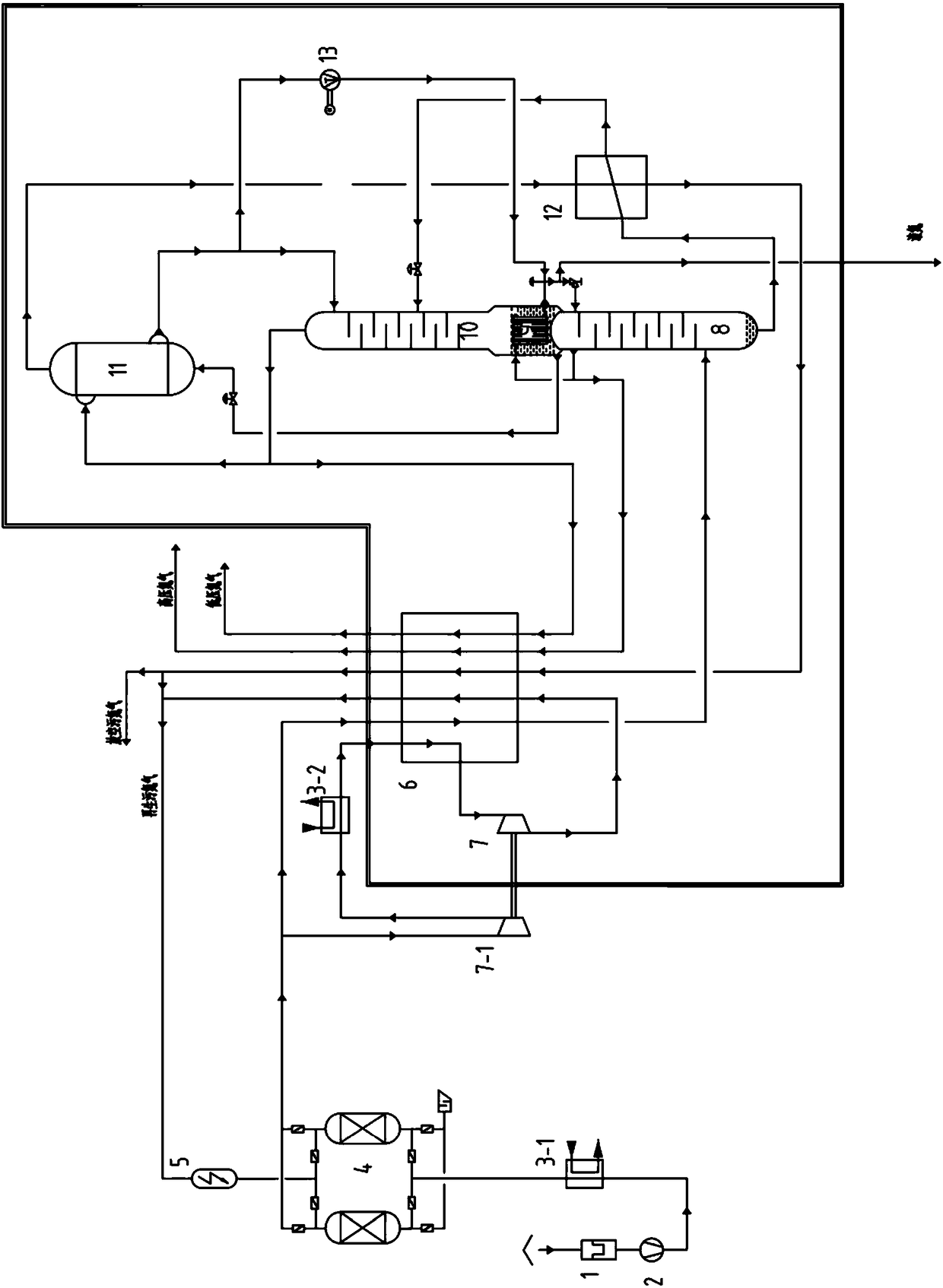
[0034] A pure nitrogen production device, such as figure 1 As shown, it includes a filter 1, a turbo air compressor 2, an air precooling unit 3-1, an alternately used molecular sieve adsorber 4, an electric heater 5, a supercharged aftercooler 3-2, and a main heat exchanger 6 , expander 7, rectifying tower I8, rectifying tower II10, condensing evaporator I9, condensing evaporator II11, subcooler 12, liquid nitrogen pump 13, cold box,

[0035] Filter 1, turbine air compressor 2, air pre-cooling unit 3-1, alternately used molecular sieve adsorber 4, electric heater 5, booster aftercooler 3-2, booster end of expander 7-1 Located outside the cold box, the main heat exchanger 6, expander 7, rectification tower I8, ...


PUM


Abstract

The invention discloses a pure nitrogen preparation device. The device comprises a filter, a turbine air compressor, an air pre-cooling unit, alternatively used molecular sieve adsorbers, an electricheater, a supercharged aftercooler, a main heat exchanger, an expansion machine, a first rectifying tower, a second rectifying tower, a first condensation evaporator, a second condensation evaporator,a subcooler, a liquid nitrogen pump and a cold box. According to the device, the cold flow needed by the device is prepared through expansion of pressured air, the air enters the second rectifying tower to participate in rectification after being expanded to a certain pressure, the extraction rate is high, and the energy consumption is low; or the air is expanded to the normal pressure, the pressure ratio is high, the refrigerating capacity efficiency is high, the refrigerating capacity is large, the starting time of the device can be shortened, the electricity consumption is saved, the extraction rate is higher, the energy consumption is lower, the high-pressure nitrogen is discharged out of the cold box after being reheated, the dirty nitrogen in the mixed part is used for air regeneration of alternatively used molecular sieve adsorbers, the oxygen content in the regenerated dirty nitrogen is reduced, and the service life of the electric heater is effectively prolonged.

Description

technical field [0001] The invention relates to the technical field of air separation, in particular to a pure nitrogen preparation device and process. Background technique [0002] With the technological development and innovation of chemical industry, electronics, new materials, porcelain steel industry, glass and other industries, the demand for nitrogen has increased rapidly, and at the same time, higher requirements have been put forward for the purity of nitrogen. [0003] The commonly used pure nitrogen equipment on the market is divided into two types: single-tower nitrogen production and double-tower nitrogen production. The single-tower nitrogen production can produce a certain pressure of product nitrogen directly for users to use. Although the structure of this process is simple, However, the extraction rate of the device is low, and the unit consumption of the product is high, which is not suitable for the large-scale use of nitrogen; the double-tower nitrogen p...

Claims


Application Information

Patent Timeline
IPC IPC(8): F25J3/04
CPCF25J3/0406F25J3/04406F25J3/04181F25J3/04212F25J3/0429F25J3/04303F25J3/04412F25J2200/54F25J2200/92F25J2205/66F25J2235/42F25J2245/42F25J2250/02F25J2215/40
Inventor 蔡晖何森林杨正军徐贺
Owner HANGZHOU TURNING ENERGY TECH DEV CO LTD
Learn More