Protection device for stent, manufacturing method thereof, and medical device

A technology of protection device and medical device, applied in the field of medical devices, can solve the problems of increasing diameter, unable to meet the needs of maintaining the diameter size of polymer stents, etc., and achieve the requirements of avoiding damage and wear, easy sterilization, and simple operation process. Effect

Active Publication Date: 2019-11-26
SHANGHAI MICROPORT MEDICAL (GROUP) CO LTD
View PDF7 Cites 0 Cited by
  • Summary
  • Abstract
  • Description
  • Claims
  • Application Information

AI Technical Summary

Problems solved by technology

This advantageous feature results in less concern about the risk of metal stents becoming larger in diameter over time when the product is packaged waiting to be used in a medical procedure
However, polymer stents are affected by the rebound properties of polymer materials, so the original traditional single-layer protective sleeve design cannot meet the requirements of maintaining the diameter of polymer stents. The challenge of maintaining the diameter of the polymer scaffold at the desired diameter of the delivery system until the stent system is delivered to the target site in the body

Method used


Image

  • Protection device for stent, manufacturing method thereof, and medical device
  • Protection device for stent, manufacturing method thereof, and medical device
  • Protection device for stent, manufacturing method thereof, and medical device

Examples


Embodiment 1

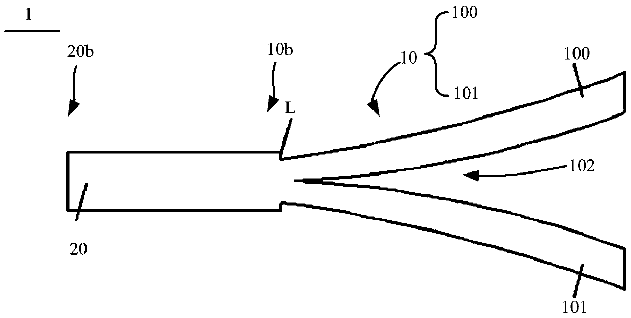
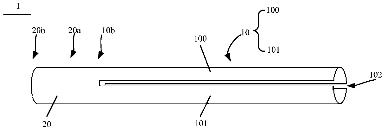
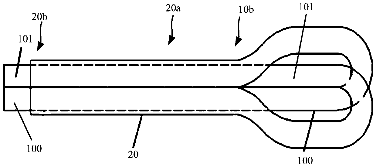
[0044] Please refer to Figure 1b , figure 2 and image 3 , the protective device of the stent of the present invention includes: a sheath, one end of the sheath forms a protective sheath 10, and the other end forms a constraining sheath 20, and the protective sheath 10 is located at the formed part of the constraining sheath 20. In the accommodating space; the bracket 2 is located in the accommodating space formed by the protective sheath 10, a connection section is included between the protective sheath 10 and the restraining sheath 20 of the sheath, and the sheath also includes everything An opening 102, the slit 102 extends along the direction of the connecting section and the protective sheath 10, the slit 102 forms the connecting section and the protective sheath 10 into a first part 100 and a second part 101 separated from each other . Wherein, the material of the bracket is Pebax, PTFE, polyethylene, polycarbonate, polyamide or nylon.

[0045] Please refer to Fi...

Embodiment 2

[0053] This embodiment provides a method for manufacturing a protective device for a stent. The method for manufacturing the protective device for a stent includes: preparing a pipe, and dividing one end of the pipe into a first separation part and a second separation part in the axial direction , the undivided end of the pipe forms a constraining sheath, the first separation part and the second separation part are placed in the lumen of the constraining sheath, and the length of the constraining sheath is less than or equal to the total length of the pipe one-third of the length. Wherein, the first separating portion and the second separating portion pass through the lumen of the first section and at least partly pass through the lumen of the first section, the advantage of this is that when the first separating portion and the second The separation part passing through the lumen of the first section will naturally separate to form an opening, so that the relative movement be...

Embodiment 3

[0056] This embodiment provides a medical device. Compared with the protective device for the stent in Embodiment 1, the medical device is different in structure. The medical device includes: a stent and a sheath, and the stent is covered by Pressed on a balloon catheter; the sheath includes a first section and a second section, the first section is a tubular structure, and the second section is divided into a first separation part and a second section through an incision The separation part, the first separation part and the second separation part are accommodated in the lumen of the first segment, and the stent and the balloon catheter are accommodated in the lumen formed by the first separation part and the second separation part middle.

[0057] In order to better understand the operation method of how to remove the bracket from the protection device, three examples are used below to illustrate several protection devices with different structures.


PUM


Abstract

The invention provides a protective device for bracket and a manufacturing method thereof and a medical device, wherein the protection device includes a sheath, one end of the sheath is form to a protective sheath, and the other end of the sheath is formed to a restraining sheath, and the protective sheath is positioned in the accommodating space formed by the restraining sheath; the bracket is positioned in the accommodating space formed by the protective sheath, a connecting section is provided between the protective sheath and restraining sheath of the sheath, the sheath also includes a cut, the cuts extend along the direction of the connecting section and the protective sheath, The cut forms the connection section and the protective sheath into a first section and a second section which are separated from each other. The protective device based on the bracket of the invention can not only provide radial binding force for the bracket, but also won't generate friction with the outersurface of the bracket when the protective device is removed from the bracket, and the whole operation process is simple when taking the lower protective device from the bracket, and the operation issimple, and the working efficiency is improved.

Description

technical field [0001] The invention relates to the technical field of medical devices, in particular to a bracket protection device, a manufacturing method thereof, and a medical device. Background technique [0002] The stent product consists of a stent body, a drug coating and a ball-expanded delivery system. It is suitable for ischemic heart disease caused by primary coronary artery disease, and can improve the inner diameter of coronary artery. [0003] The stent bodies used in the prior art include bare metal stents, drug-coated metal stents, and degradable and absorbable polymer or metal stents. [0004] Polymer stents, unlike metallic stents, are only expected to remain in the body for a limited period of time. In many therapeutic applications, the stent must remain in the body for a limited period of time until it fulfills its intended function, eg, maintaining a patency of the blood vessel. [0005] However, a number of challenges need to be overcome when develo...

Claims


Application Information

Patent Timeline
Patent Type & Authority Patents(China)
IPC IPC(8): A61F2/82A61F2/962
CPCA61F2/82A61F2/962
Inventor 李志龙田浩孙莉黄楚波罗七一
Owner SHANGHAI MICROPORT MEDICAL (GROUP) CO LTD
Why Eureka
Try Eureka