Waste heat recovery unit for intensive tobacco leaf curing room

A dense barn and waste heat recovery technology, which is applied in the field of heat transfer, can solve the constraints of large-scale promotion and application of waste heat recovery and utilization technology of exhaust air flow, involving the construction quality and technical performance of waste heat recovery system, increasing equipment cost and operating energy consumption To achieve the effect of fast construction and installation, increase of planting income, and improvement of heat energy utilization efficiency

Inactive Publication Date: 2018-06-05
陈庆山
View PDF0 Cites 0 Cited by
  • Summary
  • Abstract
  • Description
  • Claims
  • Application Information

AI Technical Summary

Problems solved by technology

[0003] However, when installing the waste heat recovery device of the exhaust air flow in the intensive barn, the frame structure and the heat pipe heat exchange system of the existing intensive barn have their own particularities. Equipment is a relatively troublesome construction operation, which involves the construction quality and technical performance of the waste heat recovery system
First of all, the positions of the moisture exhaust air outlet and the fresh air inlet of the existing intensive barn are located on the top of the tobacco leaf intensive barn, and the usual integral heat pipe heat exchanger has a large volume and weight due to the integrated structure of the evaporation section and the condensation section , it is difficult to move and install, which brings inconvenience to the installation and construction. If a large number of cluster kang rooms in the baking factory use hoisting equipment, it will increase a lot of trouble and construction costs, and waste a lot of time. The heat pipe heat exchanger and the upper row of the baking room The connection of the air port must also increase the connection of the air duct, and the fan must be added to the equipment, which will increase the equipment cost and operating energy consumption; the usual separated heat pipe heat exchange system has fast heat transfer speed, simple structure, and flexible layout. The cold and heat sources are separated to achieve long-distance heat transfer. Since the system is a separate structure, its volume and weight are relatively reduced, which is convenient for transportation and installation. However, the connection of the heat pipe between the evaporator and the radiator of the separated heat pipe waste heat recovery system On-site welding is required, and the requirements for welding pipelines and components under pressure are very high, and their weaknesses will become more prominent when the number of external connecting pipes increases; moreover, processes such as vacuuming, working fluid filling, and inspection and testing must also be carried out on-site, which means The equipment involved in vacuum equipment, welding equipment, working fluid injection and inspection and testing must be transported to the construction site, and must be moved back and forth on each barn in the flue-cured tobacco factory. Such complicated procedures and various construction equipment are on the roof. Working at heights brings a lot of trouble to the installation and construction, which not only wastes time, but also involves a large amount of construction and complicated construction process, which can easily lead to inconsistent construction quality and difficult control of product quality
The high failure rate and difficulty in construction of the waste heat recovery equipment for the exhaust air flow in the dense barn seriously restrict the large-scale promotion and application of the waste heat recovery technology for the exhaust air flow

Method used


Image

  • Waste heat recovery unit for intensive tobacco leaf curing room

Examples


Embodiment Construction

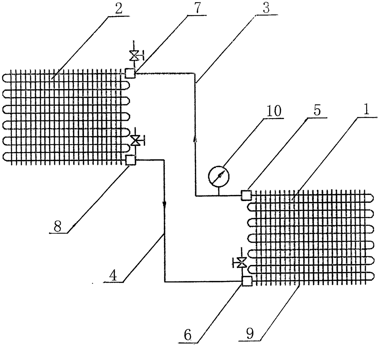
[0015] The present invention will be further described below in conjunction with accompanying drawing.

[0016] Such as figure 1 As shown, the present invention comprises: evaporator (1), radiator (2), vapor riser (3) and liquid downcomer (4); Described evaporator (1) and radiator (2) all adopt horizontal arrangement The serpentine tube series structure; the outlet of the evaporator (1) is provided with a single-function stop valve (5); the inlet of the evaporator (1) is provided with a multi-function stop valve (6) with the functions of adding liquid, stopping and connecting; the radiator (2 ) inlet is provided with a multifunctional shut-off valve (7) with functions of cut-off, connection and exhaust, and the outlet of the radiator (2) is provided with a multi-functional shut-off valve (8) with functions of cut-off, exhaust and connection. The steam rising pipe (3) is connected through a single-function stop valve (5) and a multi-function stop valve (7); the liquid downpipe...


PUM


Abstract

The invention provides a waste heat recovery unit for an intensive tobacco leaf curing room. The waste heat recovery unit comprises an evaporator (1), a heat radiator (2), a steam ascending pipe (3) and a liquid descending pipe (4). The waste heat recovery unit is characterized in that a single-function stop valve is arranged at an outlet of the evaporator (1); a multifunctional stop valve is arranged at an inlet of the evaporator (1); a multifunctional stop valve is arranged at an inlet of the heat radiator (2); and a multifunctional stop valve is arranged at an outlet of the heat radiator (2). Therefore, all manufacturing procedures of the waste heat recovery unit are completed in factory in advance, complicated procedures like welding, vacuumizing, working medium injection and inspection and test in a mounting process at a construction site are avoided, the construction efficiency is improved effectively, the construction cost is lowered, the mounting construction becomes simpler and more flexible, convenient and efficient, and mounting construction rapidness and mounting quality standardization are realized.

Description

technical field [0001] The invention relates to the field of heat transfer, in particular to a waste heat recovery unit used in a dense tobacco barn. Background technique [0002] Tobacco leaf curing is an energy-intensive operation. During the tobacco leaf curing process, moisture must be removed in a timely manner. The moisture removal process in the barn is one of the key processes in tobacco leaf curing. The humidity exhaust airflow not only has a high relative humidity, but also The temperature is higher than the ambient air temperature, carrying a large amount of low-temperature waste heat, and the heat loss of the exhaust air flow in the dense barn is usually about 20% of the calorific value of the fuel, and can reach more than 25% in severe cases. Adding the waste heat recovery system of the exhaust air flow in the intensive tobacco curing barn is an important method to realize energy saving and emission reduction in flue-cured tobacco production. Practical signific...

Claims


Application Information

Patent Timeline
Patent Type & Authority Applications(China)
IPC IPC(8): F28D15/02
CPCF28D15/02
Inventor 陈庆山孙永军曹晓涛
Owner 陈庆山
Why Eureka
Try Eureka