Floating wave power generation device

A wave power generation and floating technology, applied in wind power generation, hydropower generation, floating buildings, etc., can solve the problems of high transmission cost, not a long-term safety plan, and the inability of self-sufficiency in living materials.

Inactive Publication Date: 2018-06-08
钟声
View PDF0 Cites 9 Cited by
  • Summary
  • Abstract
  • Description
  • Claims
  • Application Information

AI Technical Summary

Problems solved by technology

Take our South China Sea as an example. Most of the islands here are far away from the mainland. They are often not self-sufficient in living materials because of their small size. Everything has to be resupplied by ships or planes traveling thousands of kilometers. Even a drop of fresh water is precious! The people here have to endure the harsh environment and lack of supplies all year round, and even go hungry when the sea conditions are bad and the storms are too strong, and the supplies cannot be delivered in time! If there is a way to help them improve their living and working conditions, that would be great! Of course, there are many ways under modern technology, but none of them can avoid a key problem, at least need electric energy to handle it! Electricity can run seawater desalination equipment to produce fresh water, drive air conditioners to adjust the temperature, start refrigerators to preserve food, drive drilling rigs to detect resources, and start radars to protect territories... and so on, all kinds of electronic and electrical equipment need electricity. Be created to change! Do you want to send electricity from the mainland? The distance of thousands of kilometers is too expensive for line transmission and it is unrealistic to be easily damaged. It is best to produce it locally.
Existing conventional power generation equipment must rely on fuel to operate normally. These are only expedients, not long-term safe solutions

Method used


Image

  • Floating wave power generation device
  • Floating wave power generation device
  • Floating wave power generation device

Examples


Embodiment Construction

[0031] specific implementation plan

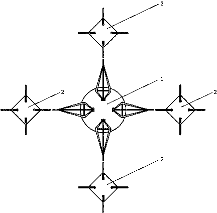
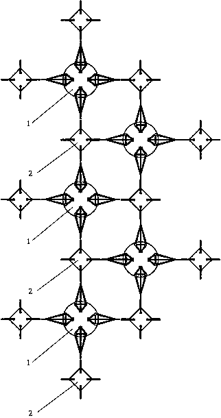
[0032] Below to figure 1 One main buoy is cross-symmetrically arranged with four auxiliary buoys to form a functional structure unit as an example, combined with figure 2 , image 3 , Figure 4 , Figure 5 , Image 6 Each functional component marked in , and its specific operation mode is simulated as follows:

[0033] when there is no wind and no waves like figure 1 As shown, the main buoy 1 and the four auxiliary buoys 2 arranged symmetrically in a cross are in a state of static equilibrium, and the system does not perform work; when the wind and waves come, one of the front auxiliary buoys first floats up with the wave crest, and at this time the main buoy is due to The relationship between the upper and the rear is still in a position lower than that of the auxiliary buoy, and the asynchronous change of its position breaks the original balance. The rocker arm 4 on the main buoy is driven by the connecting rod 7 at one end of the a...


PUM


Abstract

The invention relates to a floating platform capable of suspending in water, a device of generating electricity by means of wave energy of water. Simply, the device is composed of large and small floating tables with different functions and divisions of work. The combination can be diversified, and in particular, the most typical structure of an integral functional unit is formed by four secondaryfloating tables which are arranged symmetrically on a primary floating table in a cross manner. Compared with wind power generation, the device without a firm foundation is conveniently built, and isexcellent in windproof and wave-resisting performances as the device is attached to the water surface. Compared with solar power generation, the layout of the device does not occupy limited land area, and is also not limited by lighting conditions in cloudy days at night. Furthermore, the floating platform formed on the water surface combines the expanded land area and wind energy or solar energy, so that the device is a possible vision. In a word, the floating wave power generation device not only is suitable for islands or drilling platforms far from the main land, but also has a glorious prospect if being applied to peri-urban areas rich in coastal tide or wave resource and exuberant in demand on energy source on a large scale.

Description

technical field [0001] The invention relates to the field of energy technology, in particular to a device for converting wave energy into electric energy in new energy sources. Background technique [0002] With the increasing demand for energy in human production and life, and because traditional energy sources such as coal and oil are facing resource depletion and environmental pollution in use, people are beginning to focus more on water in order to develop more new energy. Energy, wind energy, light energy and other clean energy. We often see hydropower stations built across rivers, huge arrays of solar panels on plateaus, and wind power generators standing all the way on the grasslands, but it is rare to see such spectacular scenes on the sea where the waves and tides are never calm. Seventy percent of the earth's surface area is covered by oceans, and people are increasingly shifting their attention from the limited land area to the infinite ocean space. How to devel...

Claims


Application Information

Patent Timeline
Patent Type & Authority Applications(China)
IPC IPC(8): F03B13/16B63B35/44
CPCF03B11/00F03B13/16F03B13/20B63B35/44B63B2035/4466B63B2209/14F05B2250/72F05B2260/421F05B2260/406F05B2270/20Y02E10/727Y02E10/20Y02E10/30F05B2270/202B63B1/048F05B2240/40F03B13/1805
Inventor 钟声
Owner 钟声
Why Eureka
Try Eureka