A light-emitting device, packaging method, and projection system

A light-emitting device and packaging method technology, which is applied in the field of lighting and display, can solve the problems of debonding, large structural stress, and the addition ratio of high thermal conductivity fillers should not be too high, and achieve the effect of high packaging and high reliability performance

Active Publication Date: 2020-12-08
APPOTRONICS CORP LTD
View PDF4 Cites 0 Cited by
  • Summary
  • Abstract
  • Description
  • Claims
  • Application Information

AI Technical Summary

Problems solved by technology

[0003] The traditional technology is to use high thermal conductivity bonding glue. Its main components are organic bonding resin materials and high thermal conductivity inorganic fillers. This kind of glue material has a common disadvantage: the thermal conductivity increases with the increase of inorganic thermal conductivity fillers. However, the bonding force becomes stronger with the increase of organic resin materials; in order to ensure effective bonding, the addition ratio of high thermal conductivity fillers in this glue should generally not be too high, and the thermal conductivity of the glue is 4W / (m·K ) or less; glue with thermally conductive fillers has a higher hardness after curing, resulting in greater structural stress. In the working environment of cold and hot cycles, there are problems such as degumming and cracking, which cause hidden dangers to product reliability.

Method used


Image

  • A light-emitting device, packaging method, and projection system
  • A light-emitting device, packaging method, and projection system
  • A light-emitting device, packaging method, and projection system

Examples


Embodiment 1

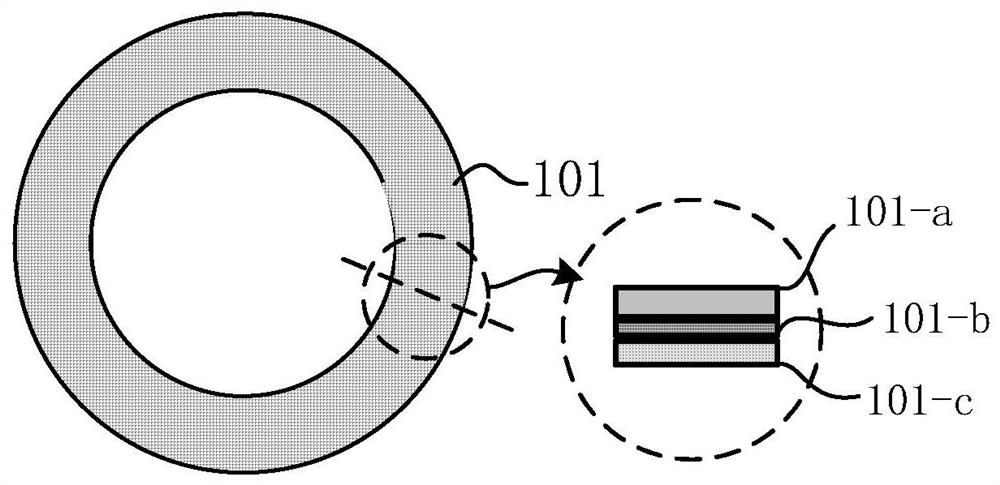
[0042] In this embodiment, a reflective layer and a light-emitting layer on the surface of the reflective layer are printed on one side of a ring-shaped ceramic substrate, such as figure 1 As shown, the ceramic wheel includes a light-emitting layer 101-a, a reflective layer 101-b, and a ceramic substrate 101-c; the whole constitutes the ceramic wheel 101.

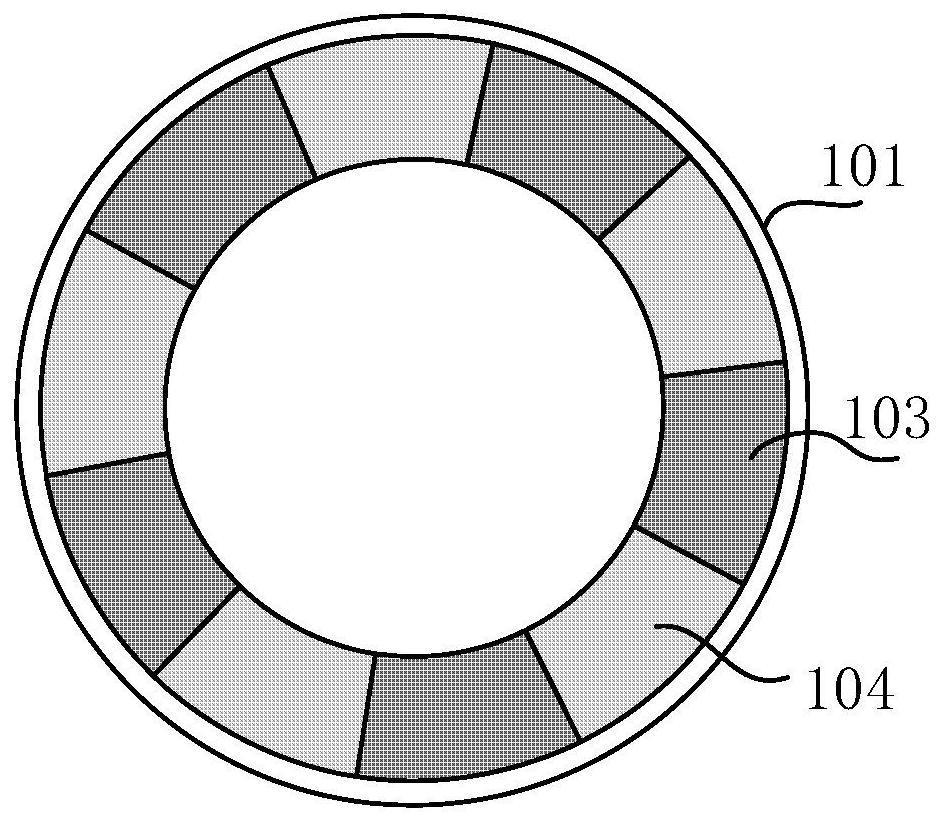
[0043] like figure 2 As shown, on the other side of the ceramic wheel, follow the figure 2 The distribution shown is schematic, that is, the area of ​​high thermal conductivity glue 103 and the area of ​​low thermal conductivity glue 104 are distributed at intervals along the circumferential direction, and high thermal conductivity glue 103 (thermal conductivity greater than 10w / (m k)) and strong adhesion are alternately coated respectively. Low thermal conductivity glue 104 (thermal conductivity less than 10w / (m k)), requires high thermal conductivity glue 103 area S 103 ≥S 104 , and 70%*S 104+103 ≥S 103 ≥50%*S 104...

Embodiment 2

[0047] In this embodiment, a reflective layer and a light-emitting layer on the surface of the reflective layer are printed on one side of a ring-shaped ceramic substrate, such as figure 1 As shown, the ceramic wheel includes a light-emitting layer 101-a, a reflective layer 101-b, and a ceramic substrate 101-c; the whole constitutes the ceramic wheel 101.

[0048] like Figure 4 As shown, on the other side of the ceramic wheel, follow the Figure 4 The distribution shown is schematic, that is, the area of ​​the high thermal conductivity glue 103 and the area of ​​the low thermal conductivity glue 104 are distributed in a concentric ring at intervals, and the high thermal conductivity glue 103 and the low thermal conductivity glue 104 with strong adhesion are respectively dispensed (or printed). Requires high thermal conductivity glue 103 area S 103 ≥S 104 , and 70%*S 104+103 ≥S 103 ≥50%*S 104+103 .

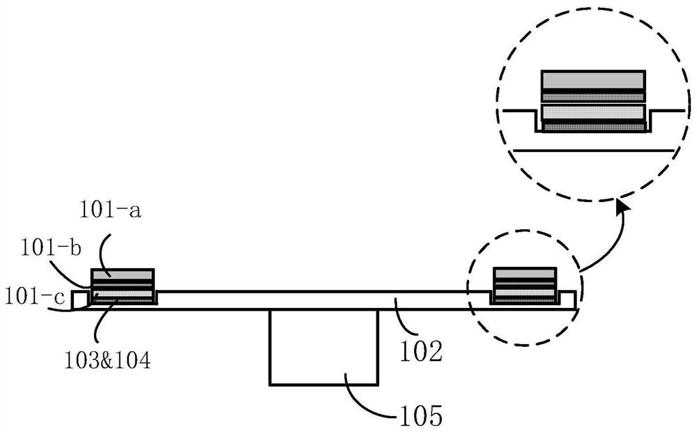
[0049] like Figure 5 As shown, the opposite surface of the high ther...


PUM

PropertyMeasurementUnit
thermal conductivityaaaaaaaaaa
hardnessaaaaaaaaaa
hardnessaaaaaaaaaa

Abstract

Provided are a light emitting device, a packaging method and a projection system, wherein the light emitting device comprises at least two components that are adhesively packaged together, and an interface of a bonded substrate of the components is divided into at least a first functional zone coated with a high thermal conductivity glue (103) and a second functional zone coated with a low thermal conductivity glue (104), wherein the thermal conductivity of the high thermal conductivity glue (103) is greater than the thermal conductivity of the low thermal conductivity glue (104), but the low thermal conductivity glue (104) has a higher adhesiveness than the high thermal conductivity glue (103). The light emitting device meets the requirement of high thermal conductivity bonding while ensuring high-strength adhesive performance, thereby achieving high reliability of the light emitting device.

Description

technical field [0001] The invention relates to the technical field of illumination and display, in particular to a light emitting device, a packaging method and a projection system. Background technique [0002] As we all know, blue excitation light emitted by a solid-state light source such as LED or laser diode (LD, Laser Diode) can be used to excite yellow or green phosphor materials to obtain light of corresponding color. When this short-wavelength excitation light source excites the fluorescent material to undergo wavelength conversion to obtain long-wavelength corresponding color light, part of the energy is also converted into heat and released. As the optical power of the excitation light increases, the luminous flux of the converted colored light continues to increase, and the accompanying heat also increases continuously. The accumulation of a large amount of heat makes the temperature of the fluorescent material continue to rise, thus affecting the quantum conver...

Claims


Application Information

Patent Timeline
Patent Type & Authority Patents(China)
IPC IPC(8): H01L33/48H01L33/44H01L27/146
CPCH01L27/146H01L27/1462H01L33/44H01L33/48H01L2933/0025
Inventor 李乾陈雨叁许颜正
Owner APPOTRONICS CORP LTD
Why Eureka
Try Eureka