
High strength rotor shaft forging for high voltage motor and heat treatment machining method

A high-voltage motor, processing method technology, used in heat treatment furnaces, heat treatment equipment, furnace types, etc.

Active Publication Date: 2018-06-12
宝鼎重工有限公司
View PDF5 Cites 3 Cited by
  • Summary
  • Abstract
  • Description
  • Claims
  • Application Information

AI Technical Summary

Problems solved by technology

At present, there are still technical bottlenecks in the manufacture of large-scale high-voltage motors in China, such as the stability of the overall motor during high-speed operation, and the compatibility of internal key components, etc., all need further research and analysis

Method used


Image

  • High strength rotor shaft forging for high voltage motor and heat treatment machining method
  • High strength rotor shaft forging for high voltage motor and heat treatment machining method
  • High strength rotor shaft forging for high voltage motor and heat treatment machining method

Examples


Embodiment 1

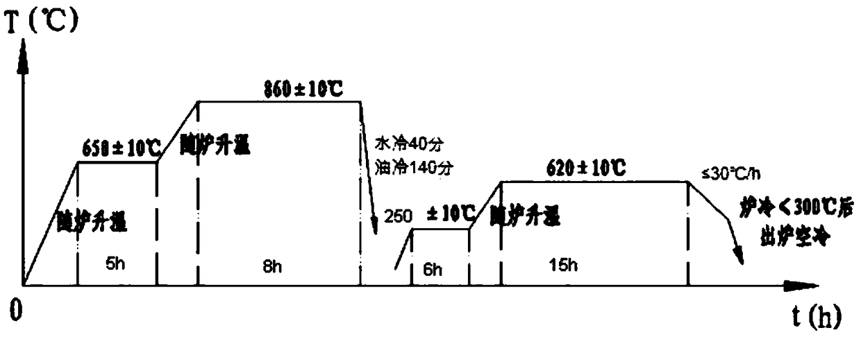
[0019] Embodiment 1: with reference to attached Figure 1-5 . A high-strength rotor shaft processing method for a high-voltage motor, (1) The mass percentage of the rotor shaft material: C 0.30-0.36%, Si0.17-0.37%, Mn0.25-0.50%, P and S≤0.020%, Cr1 .30-1.60%, Mo0.20-0.35%, Ni 1.30-1.60%, V0.04-0.10%;

[0020] (2) Heat treatment and tempering after forging:

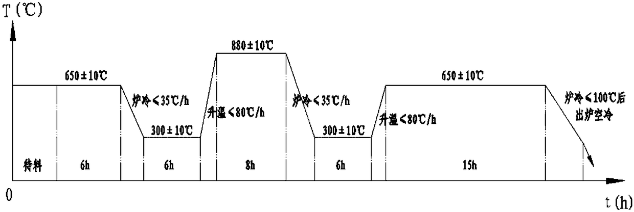
[0021]a. Post-forging heat treatment: After the forging of the forging is completed, it should be air-cooled to an annealing furnace where the surface of the forging is 650°C, and kept at 650°C for 6 hours to eliminate the stress generated during forging, and then the heat treatment should be less than 35°C / h The cooling rate is cooled to 300°C and kept at 300°C for 6 hours to fully transform the austenite structure of the forging; after the heat preservation at 300°C is completed, it is heated to 880°C at a speed of no more than 80°C / h and held at 8 hours. After fully austenitizing the inside of the workpiece, furnace ...


PUM


Abstract

The invention discloses relates to a machining method for a high strength rotor shaft for a high-voltage motor, and the machining method can meet the requirements of operating stability of a rotor shaft of a high-voltage motor under the premise of the diameter of the rotor shaft of the high-voltage motor up to 1040 mm. The rotor shaft machining method comprises the steps that 1, the roundness of abearing guard are required to be controlled at 0.006 mm, when a numerical control lathe is machined, a center frame support roller tooling is improved to be a planar bearing bush made of babbitt alloy, and a friction mode is changed from rolling friction to sliding friction; and after a process is transferred to a grinding machine for fine grinding, when the amount to be grinded is 0.3 mm, staticaging treatment is carried out for 1 week, and the machining is in place according to a required size; 2, at a bearing guard area with the highest axial requirements, namely, when the plane degree is0.012 mm, the vertical degree is 0.012 mm relative to the bearing guard, and the roughness of the end surface of a bearing bush is below 0.63, integrated combined machining of the plane and the end surface is adopted, grinding wheel positioning is adopted for precise control, the surface of a grinding wheel is trimmed to a small contact surface of an inverted cone with a diamond grinding wheel cutter, and during machining, the surface of the bearing bush is grinded by a feeding mode to ensure that the planeness is controlled at 0.008 mm and the verticality is controlled at 0.005 mm; and 3, atotal of 144 threaded holes with chamfered angles are arranged on the large outer surface of the rotor shaft, using a combination drill one-time machining and forming technology, and pre-positioning,drilling chamferings, and drilling thread bottom holes are completed in one step.

Description

technical field [0001] The invention relates to a high-strength rotor shaft processing method for a high-voltage motor that can meet the running stability requirements of the rotor shaft of a high-voltage machine under the premise that the diameter of the rotor shaft of the high-voltage motor rotor reaches 1040mm, and belongs to the field of high-voltage motor shaft manufacturing. Background technique [0002] With the continuous construction of the global marine economy and the continuous improvement of the shipbuilding industry, traditional low-voltage motors are no longer capable of meeting the needs of marine power, and are gradually being replaced by high-voltage and ultra-high-voltage motors. The high-end manufacturing of high-voltage motors has gradually reflected its importance. At present, there are still technical bottlenecks in the manufacture of large-scale high-voltage motors in China, such as the stability of the overall motor during high-speed operation, and t...

Claims


Application Information

Patent Timeline
IPC IPC(8): C22C38/44C22C38/46C22C38/02C22C38/04C21D9/28C21D6/00B23P15/14
CPCB23P15/14C21D6/004C21D6/005C21D6/008C21D9/28C22C38/02C22C38/04C22C38/44C22C38/46
Inventor 朱奇锋张林洲吕斌杰冷怡恺
Owner 宝鼎重工有限公司
Learn More