F-P cavity based MIMO (Multiple-Input Multiple-Output) antenna

An F-P and antenna technology, applied in the field of MIMO antennas, can solve the problems of large feeder network loss, large antenna array size, and difficult processing and implementation, and achieve large gains, full utilization, and large-scale effects.

Inactive Publication Date: 2018-06-12
COMMUNICATION UNIVERSITY OF CHINA
View PDF6 Cites 12 Cited by
  • Summary
  • Abstract
  • Description
  • Claims
  • Application Information

AI Technical Summary

Problems solved by technology

Therefore, in order to obtain a high-gain, multi-port MIMO system, the required antenna array size is huge
In addition, in these antenna arrays, the complex feed network design is also a big problem. In order to achieve impedance matching, the feed network needs to be designed and modified repeatedly, and the higher the gain of the antenna is, the more antenna elements are required. The more complicated the design of the power network, the greater the loss caused by the feed network, and the more difficult it is to realize the actual processing
Therefore, it is very challenging to obtain a compact, high-gain, multi-port MIMO antenna design

Method used


Image

  • F-P cavity based MIMO (Multiple-Input Multiple-Output) antenna
  • F-P cavity based MIMO (Multiple-Input Multiple-Output) antenna
  • F-P cavity based MIMO (Multiple-Input Multiple-Output) antenna

Examples


Embodiment 1

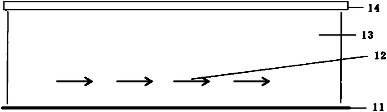
[0031] Such as figure 1 As shown, it proposes a MIMO antenna based on an F-P cavity, and the antenna includes the following structure: a metal floor 11 , multiple excitation sources 12 , a dielectric cavity 13 , and a partially reflecting surface (Partically reflecting surface, PRS) 14 . In the structure, the dielectric cavity 13 is located between the metal floor 11 and the partially reflective surface 14, and constitutes an F-P resonant cavity structure. Multiple excitation sources 12 are placed in the medium cavity 13 between the partially reflective surface 14 and the metal floor 11 . In this way, multiple excitation sources 12 form multiple excitation ports of the MIMO antenna, thereby forming a multi-port MIMO antenna, so that the same F-P resonant cavity can be used to improve the gain of all port excitation antennas, wherein each of the multiple excitation sources 12 An excitation source may consist of a single single-polarized or dual-polarized antenna or a single-po...

Embodiment 2

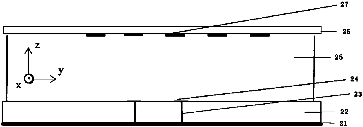
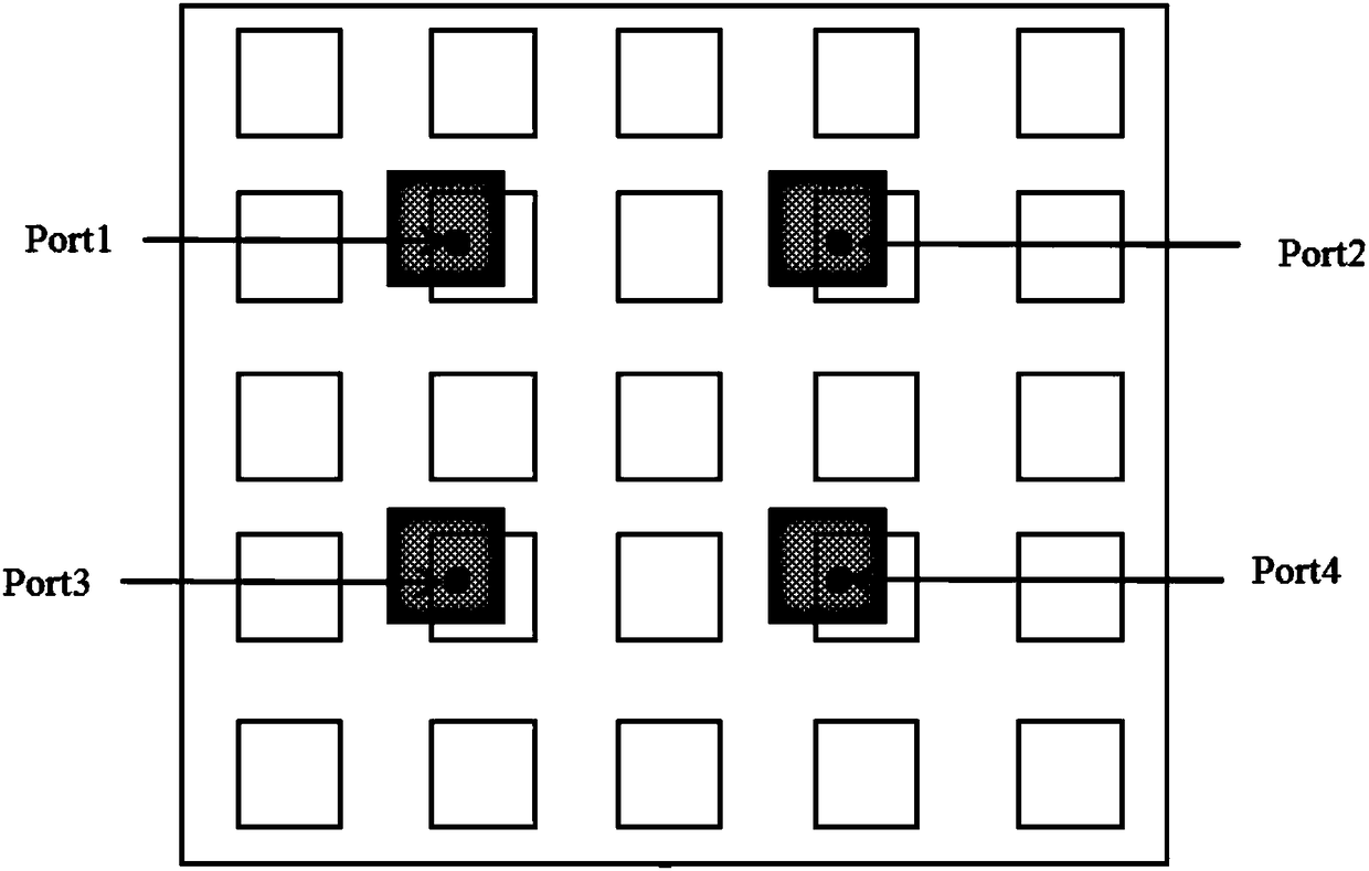
[0036] Such as Figure 2(a) , 2(b)As shown in , it shows a MIMO antenna based on F-P cavity. Figure 2(a) is a side view of the antenna structure, wherein the antenna unit includes: a metal floor 21, a bottom dielectric substrate 22, a metal via hole and a coaxial feed port 23, a metal radiation patch 24, a dielectric cavity 25, The upper dielectric plate 26 and the periodic metal patch 27, the upper dielectric plate 26 and the periodic metal patch 27 together form a partially reflective surface (Partically Reflective Surface, PRS). Among them, the metal floor 21 and the bottom dielectric substrate 22 are located at the lower part of the F-P oscillation cavity, and the partial reflection surface composed of the upper dielectric plate 26 and the periodic metal patch structure is located at the upper part of the F-P oscillation cavity. The three together constitute the F-P oscillation cavity. The plurality of metal radiation patches 24 are arranged inside the dielectric cavity ...

Embodiment 3

[0045] In the second embodiment, the metal radiation patch exists as an excitation source in the form of a single-polarized antenna. In this embodiment, the excitation form is changed from a single-polarized antenna to a dipole without increasing the size of the antenna. antenna. As shown in Figure 5(a) and Figure 5(b), on the basis of Embodiment 2, each excitation antenna in this embodiment has changed from a single-polarized antenna to a dual-polarized antenna, so that there is no need to increase the number of antennas Under the premise of reducing the size, the number of MIMO ports can be doubled, and at the same time, each port has higher gain and better isolation.

[0046] Figure 5(a) is a side view of the antenna structure, wherein the antenna unit includes: a metal floor 31, a bottom dielectric substrate 32, a metal via hole and a coaxial feed port 33, a metal radiation patch 34, a dielectric cavity 35, The upper dielectric plate 36 and the periodic metal patch 37, th...


PUM


Abstract

The invention provides an F-P cavity based MIMO (Multiple-Input Multiple-Output) antenna. The antenna structurally comprises a metal floor, a plurality of excitation sources, a medium cavity and a partially reflecting surface, wherein the medium cavity is located between the metal floor and the partially reflecting surface and forms an F-P resonant cavity structure together with the metal floor and the partially reflecting surface; and the plurality of excitation sources are placed in the medium cavity. Each excitation source can be constituted by a single single-polarized or dual-polarized antenna or be constituted by a single-polarized or dual-polarized antenna array formed by a plurality of antennas, so that the antenna space can be more sufficiently utilized under the premise of not increasing the size of the antenna on the basis of the original single-port high-gain F-P resonant cavity antenna, and a compact multi-port high-gain MIMO antenna design scheme is obtained. Therefore, alarge-scale antenna array is achieved, and each port can get high gain.

Description

technical field [0001] The invention belongs to the field of antennas, and in particular relates to a MIMO antenna based on an F-P cavity. Background technique [0002] Multiple-Input Multiple-Output (MIMO, Multiple-Input Multiple-Output) technology uses multiple antenna elements at the transmitter and receiver at the same time, combined with space-time signal processing technology, can effectively improve communication by increasing the number of transceiver antenna elements The spectral efficiency and channel capacity of the system do not require additional frequency band resources, so this technology has been widely used in the field of wireless communication. However, with the increase of high data rate wireless applications such as mobile Internet and high-definition video transmission, frequency bands below 6 GHz are already very crowded. Therefore, people have turned their attention to the millimeter wave frequency band of 30 GHz-300 GHz. Because in this frequency ba...

Claims


Application Information

Patent Timeline
Patent Type & Authority Applications(China)
IPC IPC(8): H01Q1/38H01Q1/48H01Q9/04H01Q19/10
Inventor 朴大志余海龙
Owner COMMUNICATION UNIVERSITY OF CHINA
Why Eureka
Try Eureka