Elastic beam structure PVDF modal sensor generation method

A technology of sensors and elastic beams, applied in the field of continuous distributed PVDF modal sensor generation, achieves the effects of simple signal processing, simple calculation, and strong versatility

Inactive Publication Date: 2018-06-15
HARBIN ENG UNIV
4 Cites 5 Cited by

AI-Extracted Technical Summary

Problems solved by technology

This kind of layout strategy of discrete distributed error sensors and drivers ...

Abstract

The invention provides an elastic beam structure PVDF modal sensor generation method. The method comprises the following steps of: inputting a model parameter, generating a modal sensor charge equation, generating the modal sensor charging equation into a matrix form through inputting a flexibility coefficient, a shape function and an integral matrix of a modal sensor, calculating a shape coefficient of the modal sensor and calculating a vibration mode function by using a smooth Fourier expansion method so as to generate an effective electrode shape of the modal sensor; describing Lagrangian equations of total potential energy and total kinetic energy of an elastic beam structure, solving an extreme value of an unknown coefficient by utilizing Rayleigh-Ritz, generating K and M matrixes, generating a free vibration matrix equation of the elastic beam structure, calculating a feature vector of a feature value so as to generator an unknown coefficient vector, and generating a vibration mode function secondary derivative. According to the method, PVDF modal sensor design under classical boundary conditions and any constraint conditions can be realized through adjusting rigidity valuesof boundary springs, so that the method has the advantages of being strong in universality, high in calculation precision and high in convergence speed.

Application Domain

Design optimisation/simulationSpecial data processing applications

Technology Topic

Integral matrixModel parameters +11

Image

  • Elastic beam structure PVDF modal sensor generation method
  • Elastic beam structure PVDF modal sensor generation method
  • Elastic beam structure PVDF modal sensor generation method

Examples

  • Experimental program(1)

Example Embodiment

[0061] The following examples describe the present invention in more detail.
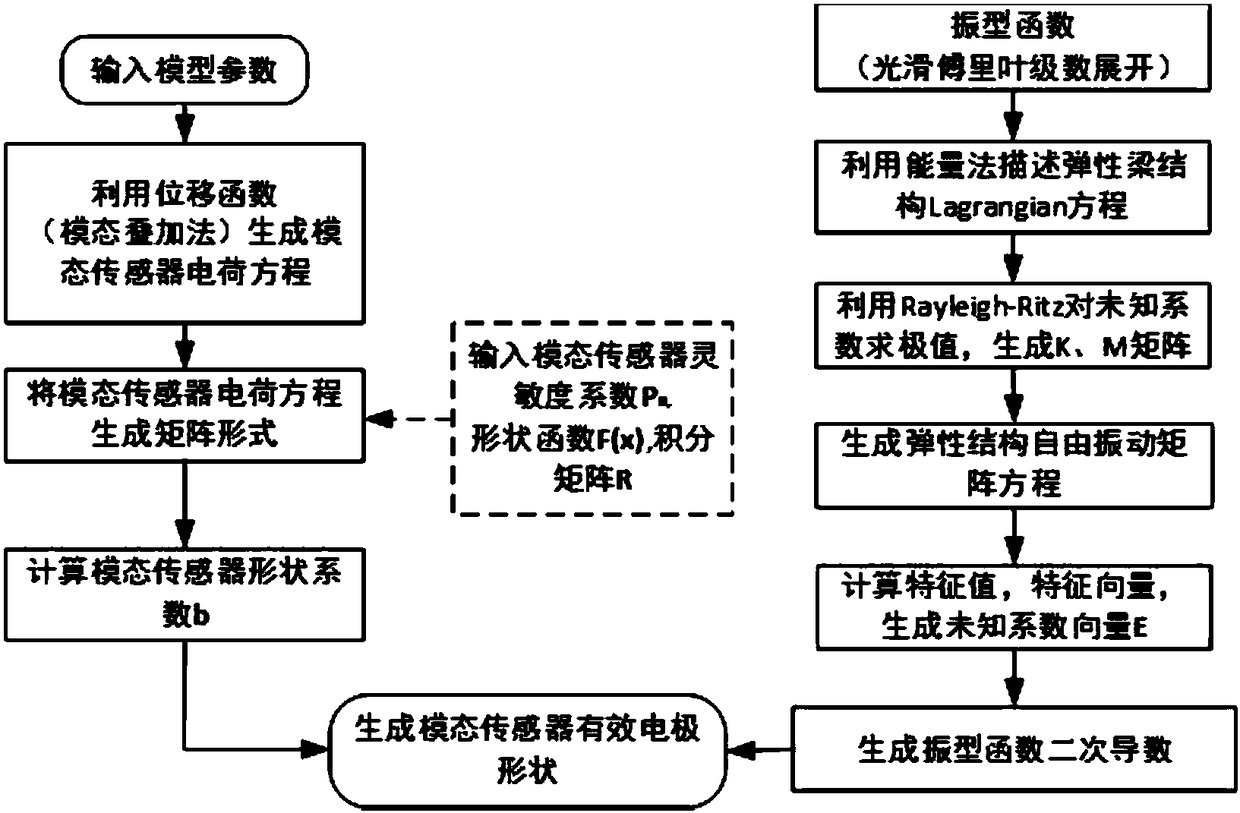
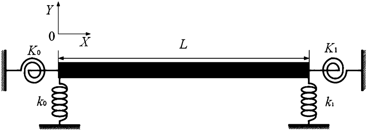
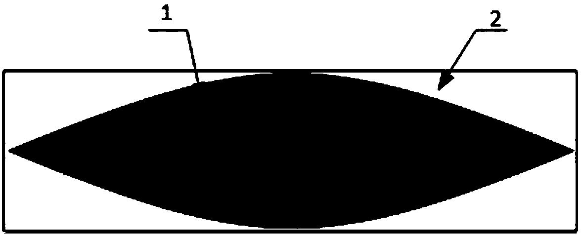
[0062] The method for generating an elastic beam structure PVDF modal sensor of the present invention relates to an effective electrode of a PVDF modal sensor that uses a smooth Fourier series method to generate an elastic boundary. The method for generating the effective electrode of the PVDF modal sensor with the elastic boundary includes: inputting model parameters, using the displacement function (modal superposition method) to generate the modal sensor charge equation, and inputting the modal sensor sensitivity coefficient P n , Shape function F(x) and integral matrix R generate matrix form of modal sensor charge equation, calculate modal sensor shape coefficient b and use smooth Fourier series expansion method to calculate modal function; among them, use smooth Fourier The series expansion method to calculate the mode function includes using the energy method to describe the Lagrangian equation of the total potential energy and total kinetic energy of the elastic beam structure, using the Rayleigh-Ritz to find the extreme value of the unknown coefficients, generating K and M matrices, and generating the free vibration matrix equation of the elastic beam structure , Calculate the eigenvalue eigenvector to generate the unknown coefficient vector E, and generate the second derivative of the mode function. Combine figure 1 The method of the present invention specifically includes the following steps:
[0063] (1) Input the geometric dimensions, material properties, boundary conditions and physical parameters of the PVDF piezoelectric film of the elastic beam structure model;
[0064] (2) Generate the charge output equation of the PVDF modal sensor with elastic beam structure, the expression is as follows:
[0065]
[0066] Among them, Q(t) is the output charge of PVDF modal sensor; h and h p Is the thickness of the elastic beam and the thickness of the PVDF piezoelectric film; e 31 Is the piezoelectric constant in the x direction; w(x,t) is the lateral displacement of the elastic beam; F(x) is the shape function of the PVDF modal sensor; L is the length of the elastic beam;
[0067] (3) Using the theory of mode superposition, the lateral displacement of the elastic beam under the harmonic excitation force can be expressed as:
[0068]
[0069] Where a m And φ m (x) are the complex modal amplitude and mode function of the m-th order structure respectively; M is the modal truncation number; e jωt Is the simple harmonic vibration time factor.
[0070] (4) Input the PVDF modal sensor sensitivity coefficient P m , Substituting the expression in step (1), get:
[0071]
[0072] among them, Is the second derivative of the mode function;
[0073] (5) Generate the matrix form of the PVDF modal sensor charge equation, the expression is as follows:
[0074] Q(t)=γe jωt aP
[0075] Among them, γ is a constant term, defined as γ=e 31 (h+h p )/2; a is the 1×M complex modal amplitude row vector; P represents the M×1 modal sensitivity column vector;
[0076] (6) Input the shape function of the PVDF modal sensor, the expression is as follows:
[0077]
[0078] (7) Substituting step (6) PVDF modal sensor shape function expression F(x) into step (4) to establish the PVDF modal sensor charge equation matrix form, at the same time, combining step (5), the expression is as follows:
[0079] Q(t)=γe jωt aP=γe jωt aRb T
[0080] Among them, R is the integral matrix, and the expression is as follows:
[0081]
[0082] (8) In particular, the PVDF modal sensor generates the medium modal sensitivity vector P m For the default value, the target mode is set to 1, and the other elements in the vector are set to 0. The specific expression is as follows:
[0083]
[0084] Among them, t represents the target order;
[0085] (9) Through the equation in step (7), calculate the unknown coefficient vector b of the PVDF modal sensor, the expression is as follows:
[0086] b=(R -1 P) T
[0087] (10) Further, in order to obtain the PVDF mode transfer shape function F(x) defined in step (6), it is necessary to solve the second derivative of the mode function. More specifically, the mode function φ(x) uses smooth Fourier The series is expanded into the standard cosine series and four correction terms, the expression is as follows:
[0088]
[0089] Among them, A 0 ,A 1 …A n ,B 1 ,B 2 ,B 3 ,B 4 Is the unknown Fourier series coefficient and the corresponding supplementary term function coefficient ξ 1 (x),ξ 2 (x),ξ 3 (x),ξ 4 (x) is a four-term supplementary function that overcomes the discontinuity of the boundary, in particular,
[0090]
[0091]
[0092] (11) Using the energy method to describe the Lagrangian equation of the total potential energy and total kinetic energy of an elastic beam structure, the specific expressions are as follows:
[0093] L=V-T
[0094] Among them, V represents the total potential energy, including the spring potential energy V spring , And the elastic beam potential energy V beam; T represents total kinetic energy,
[0095]
[0096]
[0097] Among them, EI, ρ, S respectively represent the section tensile and bending stiffness, mass density, and section area of ​​the elastic beam structure; K 0 (K 1 ), k 0 (k 1 ) Respectively represent the rotational spring stiffness at the left end (right end) and the linear spring stiffness at the left end (right end) of the boundary;
[0098] (12) Use the Rayleigh-Ritz method to find the extreme values ​​of the unknown coefficients in the expression L in step (11), generate K and M matrices, and express them as matrices:
[0099] (K-ω 2 ρSM)E=0
[0100] Among them, K is the stiffness matrix, M is the mass matrix, E is the vector of unknown coefficients of the improved Fourier series, and ω is the natural angular frequency;
[0101] E=[A 0 A 1 … A n B 1 B 2 B 3 B 4 ] T
[0102] (13) Obtain the position coefficient vector E, the mode function φ(x), and the natural frequency by using the eigenvalues ​​and eigenvectors of step (12);
[0103] (14) Generate the second derivative of the mode function;
[0104] Combine steps (6), (9) and (14) to generate the effective electrode shape of the PVDF modal sensor.
[0105] Combine figure 2 , Set the boundary spring stiffness as K 0 =K 1 = 0, k 0 =k 1 = 1e12, modal cutoff number M=45. Elastic beam structure model material Young's modulus E=200Gpa, density ρ=7800kg/m 3 , Beam length is 0.64m, width is 0.056m and thickness is 0.008m
[0106] According to the effective electrode generation method of the PVDF modal sensor of the present invention, such as Figure 3a-Figure 3d The effective electrode schematic diagram of the first four-order PVDF modal sensor with the elastic beam structure shown, in which, Figure 3a Is the first order, Figure 3b Is the second order, Figure 3c Is the third order, Figure 3d It is the 4th order. 1 represents the effective electrode, 2 represents the elastic beam sticking surface.
[0107] Although the present invention provides specific and detailed implementations in conjunction with the accompanying drawings, the present invention is not limited to the above specific implementations and application fields. The above-mentioned examples are only for a better understanding of the present invention, and are merely illustrative and instructive. , Not restrictive.

PUM

no PUM

Description & Claims & Application Information

We can also present the details of the Description, Claims and Application information to help users get a comprehensive understanding of the technical details of the patent, such as background art, summary of invention, brief description of drawings, description of embodiments, and other original content. On the other hand, users can also determine the specific scope of protection of the technology through the list of claims; as well as understand the changes in the life cycle of the technology with the presentation of the patent timeline. Login to view more.

Similar technology patents

Driving record big data auxiliary analysis system

ActiveCN112037363AEasy to calculatereliable data
Owner:山东新亮电子科技有限公司

Calculation method of bridge pile steel sleeve construction additional force

ActiveCN113175007AThe calculation method is simple and clearEasy to calculate
Owner:ZHEJIANG UNIV CITY COLLEGE

Business scheme selection method and device, electronic equipment and medium

PendingCN111651655AThe business plan is accurateEasy to calculate
Owner:PINGAN PUHUI ENTERPRISE MANAGEMENT CO LTD

Method for determining design parameters of spring return type seat

PendingCN110955939AEasy to calculate
Owner:NANTONG UNIVERSITY

Classification and recommendation of technical efficacy words

  • Versatile
  • Easy to calculate

Automobile electric control unit calibration system and method based on ASAP standard

InactiveCN101334662AVersatileResolve interface mismatch
Owner:CHONGQING UNIV OF POSTS & TELECOMM

Multi-bus automobile communication control module based on TCN

ActiveCN1889494AaccelerateVersatile
Owner:ZHUZHOU CSR TIMES ELECTRIC CO LTD

Variable capacity multi-cylinder rotary compressor and its running method

InactiveCN1955476Alow costVersatile
Owner:LG ELECTRONICS (TIANJIN) APPLIANCES CO LTD

Blood cell analyzer and analysis method

InactiveCN101407759AVersatileReagent saving
Owner:BEIJING INSTITUTE OF TECHNOLOGYGY

Phase compensation method of quantum key distribution system

ActiveCN104301101AEasy to calculateHigh Phase Estimation Accuracy
Owner:SHANGHAI JIAODA INTELLECTUAL PORPERTY MANAGEMENT CO LTD +1

Hard and brittle mud shale fracturing pressure predicting method

InactiveCN108104804AEasy to calculate
Owner:XI'AN PETROLEUM UNIVERSITY

Catenary geometric parameter detection method and system

InactiveCN107560551AEasy to calculaterun fast
Owner:CENTURAY TECH CO LTD

Out-of-focus iris image restoration method based on frequency domain parameter estimation

InactiveCN103971341AImprove iris positioning accuracy and recognition performanceEasy to calculate
Owner:BEIJING INSTITUTE OF TECHNOLOGYGY
Why Eureka
Try Eureka