
Selective embedding method based on planar electromagnetic band gap structure

An electromagnetic bandgap structure and selective technology, applied in the fields of electrical digital data processing, CAD circuit design, special data processing applications, etc., can solve the problems of impossible to prevent SSN, insufficient stopband suppression depth, complex structure, etc. Noise suppression effect, strong practical value, and the effect of satisfying structure miniaturization

Inactive Publication Date: 2018-06-19
BEIHANG UNIV
View PDF2 Cites 5 Cited by
  • Summary
  • Abstract
  • Description
  • Claims
  • Application Information

AI Technical Summary

Problems solved by technology

On the one hand, since digital integrated circuits use logic gate switching to realize logic functions, it is almost impossible to prevent the generation of SSN, even chip designers can do nothing; on the other hand, the frequency of SSN noise may extend to 20GHz, and The decoupling capacitor becomes inductive at high frequencies and presents an open circuit state, so the method of adding decoupling capacitors at high frequencies is no longer applicable
[0004] Therefore, in the design of modern high-speed hybrid circuit systems, due to the continuous improvement of system performance, circuit integration and structural miniaturization, the SSN noise frequency in PDN can reach above 20GHz, based on traditional EBG (Electromagnetic Band Gap) There are still some limitations in structural design of PDN
[0005] At present, there is no relevant literature report. There are similar technologies in domestic and foreign literature. The method of adding a large number of vias in the broken-line bridge EBG structure increases the bandwidth, but there are frequency points where noise propagation is serious in the stop band, and the stop band suppression depth is not enough, and the structure Complex; a small L-bridge EBG unit is embedded in the L-bridge EBG structure, which can achieve -40dB suppression in the frequency range of 510MHz~10.35GHz, and the structure size is 90×90×0.4mm 3 , the size is too large

Method used


Image

  • Selective embedding method based on planar electromagnetic band gap structure
  • Selective embedding method based on planar electromagnetic band gap structure
  • Selective embedding method based on planar electromagnetic band gap structure

Examples


Embodiment Construction

[0033] The present invention will be described in detail below in conjunction with the accompanying drawings and embodiments.

[0034] The present invention solves the problem of noise suppression in high-speed circuits from another angle. Although it cannot prevent the generation of SSN noise, considering that SSN noise needs to pass through a certain medium to propagate, and then be coupled to sensitive circuit modules, especially power / ground planes, Therefore, it can be considered to suppress noise propagation on the noise coupling path, and design an ultra-wideband EBG structure to suppress the noise in the PDN. All EBG structures mentioned in the present invention are planar EBG structures.

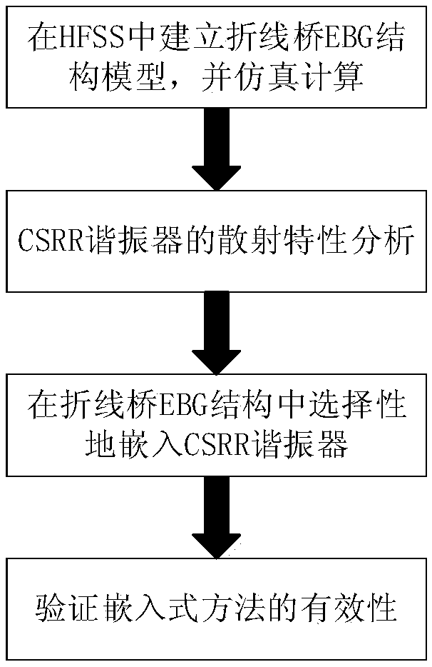
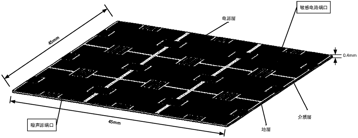
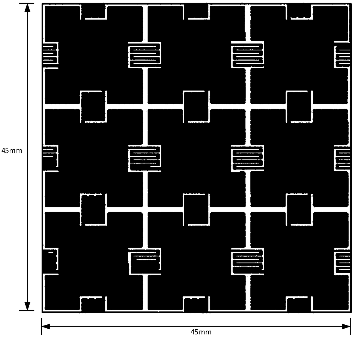
[0035] like figure 2 As shown, the specific method of the present invention is to embed a CSRR resonator near the noise source and the sensitive circuit of a 3*3 periodic broken-line bridge EBG structure. For the convenience of expression, the whole is called the EBG structure, a...


PUM


Abstract

The invention discloses a selective embedding method based on a planar electromagnetic band gap structure, and is used for enhancing the effect of inhibiting simultaneous switching noise. Firstly, a new EBG structure is designed on the basis of a broken line-shaped periodic bridge, then the scattering properties of a split ring resonator is analyzed, and meanwhile, a complementary split ring resonator (CSRR) is embedded into a special unit of the EBG structure, wherein the special unit is a unit where a noise source port and a sensitive circuit port are positioned. The research shows that thestructure can achieve more than -40 dB of inhibition on SSN noise in ultra-broadband of 0.9 GHz-36 GHz. by means of the method, the bandwidth of the EBG structure can be effectively broadened, the inhibition depth is enhanced, an equivalent circuit model of the structure is extracted, the circuit performance is analyzed, and the structural design is guided.

Description

technical field [0001] The invention relates to a selective embedding method based on a planar electromagnetic bandgap structure, which belongs to the field of microwave technology. Background technique [0002] With the rapid development of electronic technology, communication technology and computer technology, the application of high-speed circuit system is more and more extensive. Different circuit modules such as digital circuit, analog circuit, radio frequency circuit, microprocessor and memory are integrated together. The system There is an increasing demand for high performance and miniaturization. In order to provide a stable power supply voltage for each circuit module, various electronic components are directly or indirectly connected to the power distribution network (Power Distribution Network, PDN) of the system, and in the design of high-speed circuits, it is necessary to use lower High-speed DC voltage and faster rate of change to achieve Gbps-level transien...

Claims


Application Information

Patent Timeline
Patent Type & Authority Applications(China)
IPC IPC(8): G06F17/50
CPCG06F30/23G06F30/30
Inventor 苏威华贾云峰
Owner BEIHANG UNIV
Learn More