
Optical fiber cantilever beam temperature sensor based on metal coating

A technology of temperature sensor and metal coating, applied in thermometers, thermometers, instruments and other directions with physical/chemical changes, can solve the problems of decreased measurement accuracy, severe thermal deflection of bimetallic films, etc., to improve detection accuracy, small size, The effect of simple device structure

Pending Publication Date: 2018-06-22
CHINA JILIANG UNIV
View PDF2 Cites 0 Cited by
  • Summary
  • Abstract
  • Description
  • Claims
  • Application Information

AI Technical Summary

Problems solved by technology

[0005] The disadvantage of this temperature sensor is that the Fabry-Perot cavity is a closed cavity. When the sensor measures different temperatures, the gas in the cavity will shrink or expand due to temperature changes, which will cause the thermal deflection of the bimetallic film to become more severe, resulting in Measurement accuracy drops

Method used


Image

  • Optical fiber cantilever beam temperature sensor based on metal coating
  • Optical fiber cantilever beam temperature sensor based on metal coating
  • Optical fiber cantilever beam temperature sensor based on metal coating

Examples


Embodiment Construction

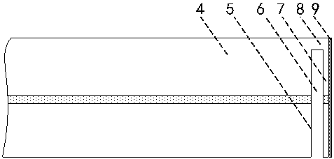
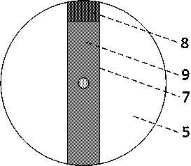
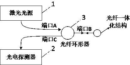
[0017] Figure 1-3 Among them, an optical fiber cantilever temperature sensor based on metal coating, including laser light source 1, photodetector 2, optical fiber circulator 3, optical fiber 4, optical fiber end face 5, Fabry-Perot cavity 6, optical fiber cantilever 7, The fixed end 8 and the metal film 9; the optical fiber cantilever 7 is located on the optical fiber end face 5, and is connected to the optical fiber end face 5 through the fixed end 8 on the edge of the optical fiber end face 5, and the optical fiber cantilever 7 and the optical fiber end face 5 form a Fabry -Perot cavity 6, forming an optical fiber integrated structure; the length of the optical fiber cantilever 7 is 90 μm-110 μm, the width of the cantilever is 20 μm-30 μm, and the thickness of the cantilever is 2 μm-5 μm. The optical fiber cantilever 7 adopts optical micromachining Process production, the preferred process is a femtosecond laser process; the metal film 9 is coated on the outer surface of t...


PUM

PropertyMeasurementUnit
Lengthaaaaaaaaaa
Widthaaaaaaaaaa
Thicknessaaaaaaaaaa

Abstract

The invention discloses an optical fiber cantilever beam temperature sensor based on metal coating, which belongs to the technical field of optical fiber sensors. The optical fiber cantilever beam temperature sensor based on metal coating comprises a laser source, a photodetector, an optical fiber circulator, an optical fiber, a fixed supporting end, an optical fiber cantilever beam, a metal film,a fabry-perot cavity and an optical fiber end surface, wherein the optical fiber cantilever beam is located on the optical fiber end surface and is connected with the optical fiber end surface through the fixed supporting end at the edge of the optical fiber end surface; the optical fiber cantilever beam is parallel with the optical fiber end surface to form the fabry-perot cavity, and an opticalfiber integration structure is formed; the outer surface of the optical fiber cantilever beam is coated with the metal film, and a two-film structure is formed; the laser source is connected with theport A of the optical fiber circulator; the optical fiber cantilever beam integration structure is connected with the port B of the optical fiber circulator; and the photodetector is connected with the port C of the optical fiber circulator. The metal film is expanded and contracted under temperature influences and two-film thermal deflection effects are generated with the optical fiber cantilever beam, the optical fiber cantilever beam generates thermal deflection, the length of the fabry-perot cavity is caused to change, light signals emitted by the laser source are reflected in the fabry-perot cavity, and under fabry-perot cavity length modulation, the reflected light signals are detected, and thus, the temperature can be detected.

Description

technical field [0001] The invention belongs to the technical field of optical fiber sensing and relates to an optical fiber cantilever beam temperature sensor based on metal coating. Background technique [0002] Optical fiber temperature sensor is one of the most commonly used temperature sensors at present. The types of fiber optic temperature sensors mainly include fiber optic grating temperature sensors, interferometric fiber optic temperature sensors, and fiber optic temperature sensors based on bending loss. Compared with traditional sensors, fiber optic sensors have many advantages, the main advantages of which are excellent performance, wide range of objects, compatibility, easy networking, and low cost. And the optical fiber is a corrosion-resistant transmission medium, which has the advantages of high sensitivity, light weight, small size, variable shape, and winding, which is beneficial to the application of aviation, aerospace and narrow spaces. The fiber opti...

Claims


Application Information

Patent Timeline
IPC IPC(8): G01K11/32
CPCG01K11/32
Inventor 刘月明徐程姜辉
Owner CHINA JILIANG UNIV
Learn More