Frequency Domain GFDM Low Complexity Minimum Mean Square Error Receiving Method and Receiver
A minimum mean square error, low-complexity technology, applied in multi-frequency code systems, digital transmission systems, baseband system components, etc., can solve problems such as the inapplicability of the AWGN channel model
- Summary
- Abstract
- Description
- Claims
- Application Information
AI Technical Summary
Problems solved by technology
Method used
Image
Examples
Embodiment 1
[0038] A frequency domain GFDM low complexity minimum mean square error receiving method, the receiving method comprises the following steps:
[0039]101: Construct K modulation vectors, perform Fourier transform on the channel matrix H to obtain a diagonal matrix, construct a filter matrix according to a given filter, and then construct a modulation matrix, and perform Fourier transformation on the modulation matrix to obtain the matrix
[0040] 102: Initialize a large matrix of all zeros, and then divide the large matrix into K 2 A sub-block Φ of size M×M i,j ;
[0041] 103: Perform two-dimensional Fourier transform on the first K / 2+1 sub-blocks on the main diagonal and the first K / 2 sub-blocks on the secondary diagonal, and then determine all other sub-blocks Φ according to the symmetric relationship i,j The two-dimensional Fourier transform result of ;
[0042] 104: For the result of two-dimensional Fourier transform Find the inverse transformation, for each sub-blo...
Embodiment 2
[0055] The scheme in embodiment 1 is further introduced below in conjunction with specific examples and calculation formulas, see the following description for details:
[0056] 201: system input;
[0057] Among them, the number of subcarriers is defined as K, the number of subsymbols as M, the filter as g, the channel matrix of the frequency selective channel as H, and the noise variance of the receiver as The GFDM receiving block of KM×1 is r, let N=KM.
[0058] 202: Construct K modulation vectors ε k , do DFT on the channel matrix H to obtain the diagonal matrix Construct the filter matrix G according to the given filter g, and then construct the modulation matrix A, and perform DFT on the modulation matrix A to obtain the matrix
[0059] Among them, ε k =diag[1,e j2πk / K ,...,e j2πk(N-1) / K ],k=0,...,K-1, (·) CT represents the conjugate transpose, is the N-point discrete Fourier transform matrix, defined as:
[0060]
[0061] Among them, W=exp(2*pi*i*x / N) / ...
Embodiment 3
[0083] The following is combined with specific mathematical formulas, examples, Figure 1-Figure 9 The scheme in embodiment 1 and 2 is further introduced, see the following description for details:
[0084] 1. GFDM system model;
[0085] 1) Transmitter model;
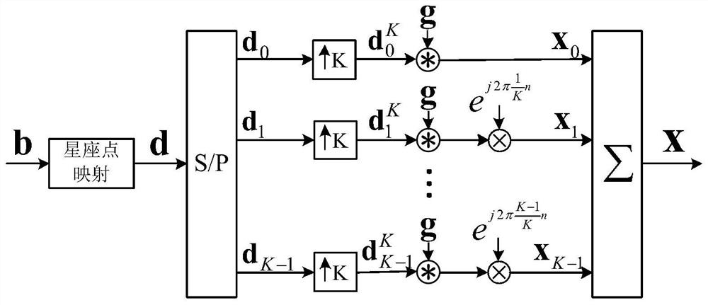
[0086] Assume that the GFDM system model contains K subcarriers and M subsymbols. Such as figure 1 As shown, after the binary source signal of length N=KM is mapped to the QAM constellation, a complex sequence d of length N is generated.
[0087] After serial-to-parallel conversion, the complex sequence d is divided into K segments of length M where d k =[d k (0),...,d k (M-1)] T . Then, each d k Do K-point upsampling to generate an upsampling sequence of length N Can be expressed as:
[0088]
[0089] Among them, δ(n) represents the unit shock function. Afterwards, the upsampling sequence with the shaping filter g=[g(0),...,g(N-1)] T Do circular convolution, then use subcarrier e j2πkn / K Do up-con...
PUM
 Abstract
Description
Claims
Application Information
 - R&D
- Intellectual Property
- Life Sciences
- Materials
- Tech Scout
- Unparalleled Data Quality
- Higher Quality Content
- 60% Fewer Hallucinations
Browse by: Latest US Patents, China's latest patents, Technical Efficacy Thesaurus, Application Domain, Technology Topic, Popular Technical Reports.
© 2025 PatSnap. All rights reserved.Legal|Privacy policy|Modern Slavery Act Transparency Statement|Sitemap|About US| Contact US: help@patsnap.com


