Ceramic product forming device and forming method

A molding device and product technology, applied in the direction of ceramic molding machines, molds, manufacturing tools, etc., can solve the problems of different molding quality of multi-cavity molds, deformation of thin-walled ceramic products, and scrapping of ceramic products in one piece, so as to shorten the molding cycle , prevent heat loss, and realize the effect of automatic production

Inactive Publication Date: 2018-06-26
LENS TECH CHANGSHA
View PDF6 Cites 0 Cited by
  • Summary
  • Abstract
  • Description
  • Claims
  • Application Information

AI Technical Summary

Problems solved by technology

In the actual production process, it is inevitable that molding raw materials will remain in the cold runner, which will increase the cost of subsequent processing
To sum up, conventional fine-gate cold runner injection molding ceramic products often have the following problems: ①difficulty filling the mold; ②deformation of thin-walled ceramic products; ③waste of raw materials in the runner; ④different molding quality of multi-cavity molds
When the device is used to prepare ceramic products, the resulting ceramic product contains flow lines, which makes the post-treatment process of the ceramic products complicated, and even makes the whole ceramic product scrap when the flow lines are deep.
The ceramic product obtained by using this device may also contain scab points, which can be located at the position corresponding to the gate or other arbitrary positions on the surface of the ceramic product (cold spots are washed to other positions during injection to form scabs) Scabs), the scabs in ceramic products containing scab points are separated from the body of the ceramic product, so such products can only be scrapped

Method used


Image

  • Ceramic product forming device and forming method
  • Ceramic product forming device and forming method
  • Ceramic product forming device and forming method

Examples


Embodiment Construction

[0030] The present invention will be further described in detail below with reference to the accompanying drawings and specific embodiments.

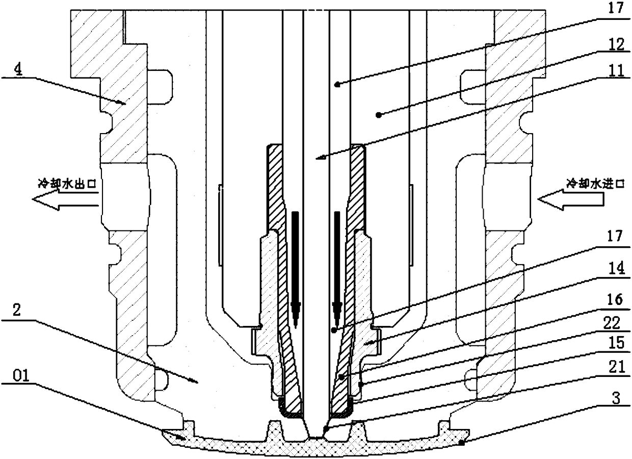
[0031] The present invention provides a Figure 1 ~ Figure 3 The ceramic product molding device shown is aimed at producing a round zirconia ceramic part with a relatively complex shape, concave-convex surface and thin-walled structure, which requires high precision and less machining.

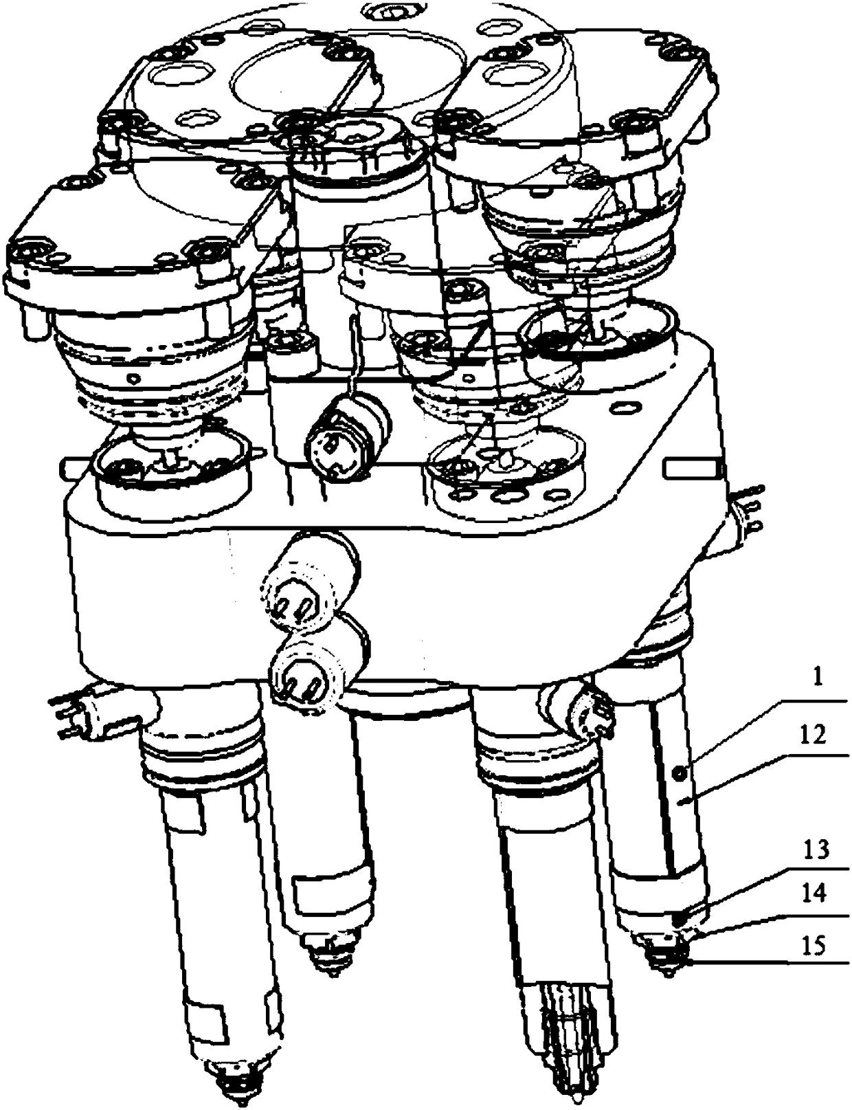
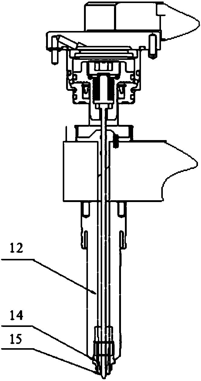
[0032]The present invention provides a molding device for ceramic products. The device includes a hot nozzle 1, a mold core insert 2, an upper mold and a lower mold. The hot nozzle includes a valve needle 11, a hot nozzle body 12, and is used The heating part 13, the titanium ring 14, the bakelite cap 15 and the high thermal conductivity ring 16 heated by the molding raw material, the thermal conductivity of the material used in the high thermal conductivity ring is greater than the thermal conductivity of the material used in the hot nozzle body; In t...


PUM

PropertyMeasurementUnit
thicknessaaaaaaaaaa
thicknessaaaaaaaaaa
surface roughnessaaaaaaaaaa

Abstract

The invention provides a ceramic product forming device. The ceramic product forming device comprises a hot nozzle, mold core inserts, an upper mold and a lower mold, wherein the hot nozzle comprisesa valve needle, hot nozzle bodies, heating parts, titanium rings, phenolic plastics caps and high heat conduction rings, wherein the heating part is used for heating a forming raw material in the hotnozzle a hot runner is arranged in the hot nozzle, the valve needle penetrates through the hot runner, and a needle point of the valve needle extends out of the hot runner; and the mold core inserts are arranged on the radial outer sides of the hot nozzle bodies, and a sprue matched with the needle point is arranged at one axial end of the mold core inserts, and the distance between the needle point and the sprue is used for controlling fluidity and static state of the forming raw material. The invention further provides a ceramic product forming method. According to the ceramic product forming device and forming method, an injection pressure loss in an injection molding process is small, heat loss is small, and the fluidity of the forming raw material is good, the produced ceramic productdoes not generate a flow line and scab and the quality of the product is guaranteed.

Description

technical field [0001] The invention relates to the processing field of ceramic products, in particular to a molding device and a molding method for ceramic products. Background technique [0002] Ceramic powder injection molding is a branch of modern powder injection molding technology and a new molding technology developed from modern powder injection molding technology. This technology has the advantages of one-time molding of products with complex shapes, high dimensional accuracy, no or little need for mechanical processing, and reduced preparation costs. [0003] The basic process of ceramic injection molding is to mix ceramic powder and appropriate binder system at a certain temperature according to a certain ratio to form a uniform injection-type feeding material, and inject it into a special mold cavity on the injection machine. And make the injection green embryo of desired shape. In theory, any form of ceramic powder raw materials, such as silicon nitride, silic...

Claims


Application Information

Patent Timeline
Patent Type & Authority Applications(China)
IPC IPC(8): B28B1/24B28B7/00
CPCB28B1/24B28B7/0097
Inventor 周群飞饶桥兵汪文才
Owner LENS TECH CHANGSHA
Why Eureka
Try Eureka