

Coating cutter shaft with diamond abrasive grain layer
A technology of diamond and abrasive grains, which is applied to the coated cutter shaft with diamond abrasive grain layer and its manufacturing field, which can solve the problems of poor wear resistance of the cutter shaft, and achieve the effects of long service life, stable cutting glass, and high holding force
Pending Publication Date: 2018-06-29
JIAXING WORLDIA DIAMOND TOOLS CO LTD
View PDF0 Cites 3 Cited by
- Summary
- Abstract
- Description
- Claims
- Application Information
AI Technical Summary
Problems solved by technology
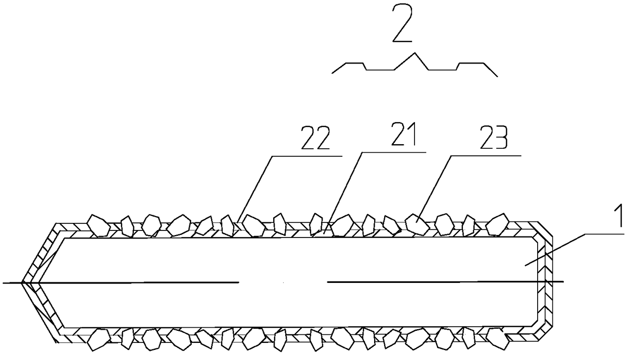
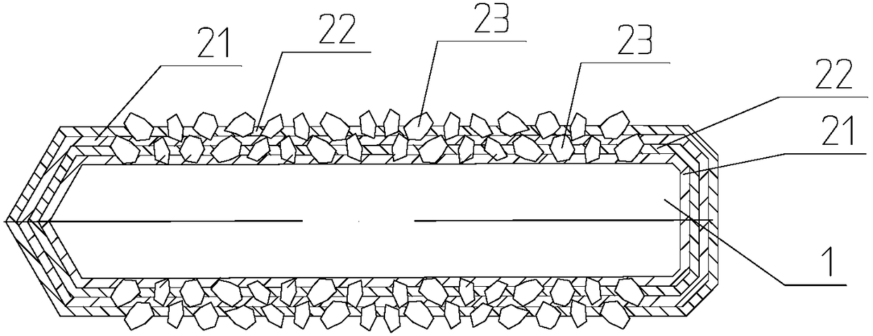
[0005] In order to solve the problem of poor wear resistance of the cutter shaft, the application provides a coated cutter shaft with a diamond abrasive layer, the coated cutter shaft includes a cutter shaft body and a diamond abrasive layer fixedly arranged on the surface of the cutter shaft body, The exposed height of each diamond abrasive grain in the diamond abrasive grain layer is similar, and at least one layer of diamond abrasive grain layer can also be set between the diamond abrasive grain layer and the cutter shaft body.
Method used
View moreImage
Smart ImageViewing Examples

Examples
Embodiment Construction
[0031] The technical solutions in the embodiments of the present invention will be clearly and completely described below in conjunction with the accompanying drawings in the embodiments of the present invention. Obviously, the described embodiments are only some, not all, embodiments of the present invention. Based on the embodiments of the present invention, all other embodiments obtained by persons of ordinary skill in the art without creative efforts fall within the protection scope of the present invention.
Login to View More PUM
| Property | Measurement | Unit |
|---|---|---|
| particle diameter | aaaaa | aaaaa |
| particle diameter | aaaaa | aaaaa |
| particle diameter | aaaaa | aaaaa |
Abstract
The invention provides a coating cutter shaft with a diamond abrasive grain layer. The coating cutter comprises a cutter shaft body and a diamond grinding grain layer fixedly arranged on the surface of the cutter shaft body, the coating cutter shaft has higher holding force to the cutter flywheel, relative to the common metal cutter shaft, the coating cutter shaft with the diamond abrasive grain layer is good in wear resistance, the service life is long, and the cutter flywheel installed by using the coating cutter shaft is more stable in glass cutting. The invention further provides a methodfor manufacturing the coating cutter shaft, and specifically, a braze welding sub-layer is brazed to the surface of a cutter shaft body, and then a titanium carbide sub-layer is deposited on the brazing sub-layer in a physical vapor deposition mode, raw materials used by the method are wide in source, the diamond abrasive particles can be uniformly brazed on the surface of the cutter shaft body byusing the method, and a titanium carbide sub-layer can be uniformly arranged on the surface of the brazing sub-layer. The method is simple and convenient, the conditions are mild, the diamond abrasive particles are firmly and stably arranged in the brazing sub-layer and the titanium carbide sub-layer.
Description
technical field [0001] The application belongs to the field of diamond abrasive tools, and in particular relates to a coated cutter shaft with a diamond abrasive grain layer and a manufacturing method thereof. Background technique [0002] The cutter body used for cutting glass mainly includes a cutter wheel, a cutter shaft and a knife holder. The movement of the knife wheel rotates around the knife axis, thereby forming scratches on the glass surface, and then the glass is cut through other processing. [0003] The cutter shaft is usually made of hard metal, alloy or PCD material. The glass shavings generated during the glass cutting process will enter the gap between the cutter shaft and the cutter wheel. As the cutter wheel rotates, it will be clamped between the cutter shaft and the cutter wheel. The glass shavings between them will wear the metal cutter shaft or the PCD cutter shaft, causing the running track of the cutter wheel to deviate from the straight line, which...
Claims
Login to View More Application Information
Patent Timeline
 Patent Type & AuthorityApplications(China)
IPC IPC(8): B28D7/00C23C14/06
CPCC23C14/0635B28D7/00
Inventor唐文林刘连东李玉婷郎海艳
OwnerJIAXING WORLDIA DIAMOND TOOLS CO LTD