3D solid-state area array laser radar and distance measuring method thereof

A laser radar and solid-state technology, applied in the direction of measuring devices, radio wave measuring systems, electromagnetic wave re-radiation, etc., can solve the problems of affecting the distance measurement accuracy, limiting the distance range of measurement, and large installation and adjustment workload, so as to improve the accuracy Accuracy and work efficiency, increased distance range and accuracy, and the effect of improved accuracy

Pending Publication Date: 2018-06-29
BEIJING INSTITUTE OF TECHNOLOGYGY
View PDF0 Cites 12 Cited by
  • Summary
  • Abstract
  • Description
  • Claims
  • Application Information

AI Technical Summary

Problems solved by technology

However, it has the problems of built-in mechanical rotating parts, complex structure, heavy installation and adjustment workload, large volume, high cost, low frame rate and low resolution.
[0004] Solid-state array lidar has a simple structure, no mechanical rotating parts, high resolution and high frame rate, but the existing solid-state array lidar uses infrared LED light source, which has a large emission field of view, poor straightness and uniformity, and poor focus The design of the optical path is complex, and the emitted optical signal becomes weaker after a long distance, which limits the distance range of the measurement and affects the accuracy of the measurement
In addition, there is a certain part of the ambient light that is close to the wavelength band of the emitted light, which will affect the distance measurement accuracy

Method used


Image

  • 3D solid-state area array laser radar and distance measuring method thereof
  • 3D solid-state area array laser radar and distance measuring method thereof
  • 3D solid-state area array laser radar and distance measuring method thereof

Examples


Embodiment 1

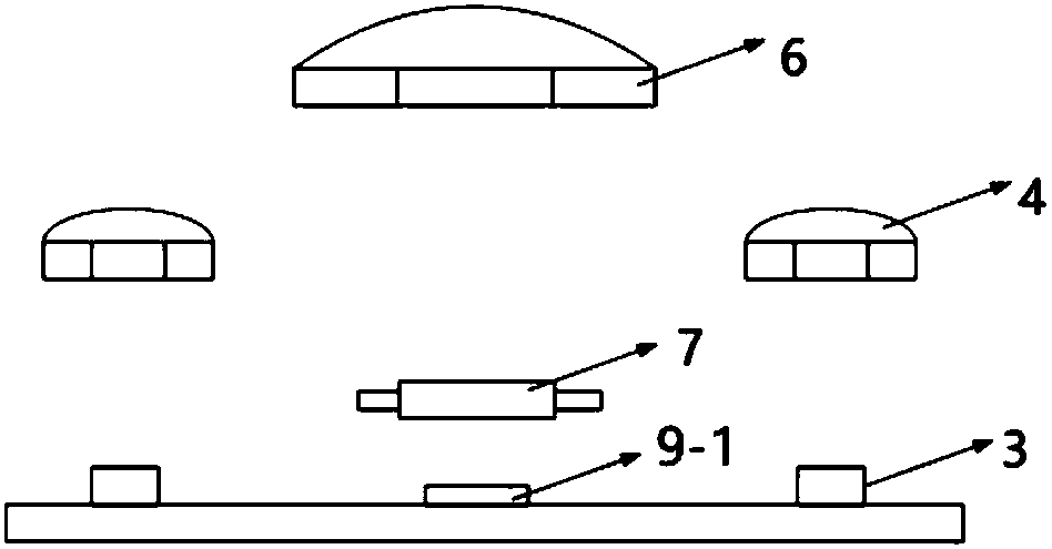
[0045] Embodiment 1: This embodiment is a three-dimensional solid-state area laser radar with a narrow field of view. The front view of the structure is as follows figure 1 As shown, it includes a light source driving module 1, a laser module transmitting end, a laser receiving lens 6 and a laser photoelectric receiving processor 9-1;

[0046] The light source driving module 1 drives the transmitting end of the laser module to emit a modulated infrared laser signal;

[0047] The emitting field angle 13 of the emitting end of the laser module is equal to the receiving field angle 14 of the laser receiving lens 6, and is less than 20°, such as Figure 5 shown;

[0048] The laser receiving lens 6 receives and focuses the reflected or scattered laser echo signals, and focuses the laser echo signals to the laser photoelectric receiving processor 9-1;

[0049] The laser photoelectric receiving processor 9-1 is located on the focal plane of the laser receiving lens 6, demodulates t...

Embodiment 2

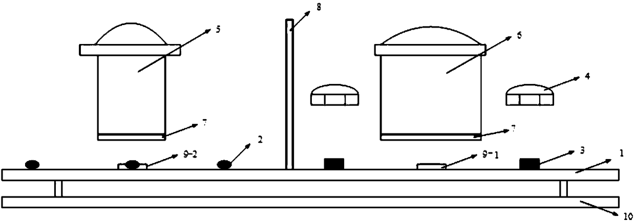
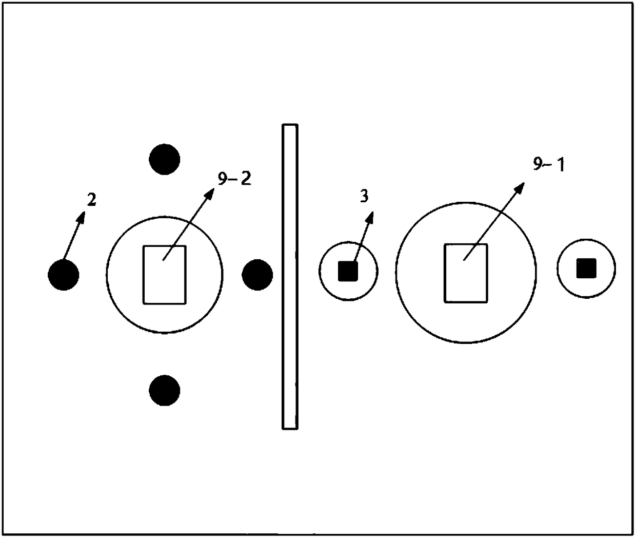
[0055] Embodiment 2: On the basis of Embodiment 1, the present invention also provides a three-dimensional solid-state area laser radar that can realize dual fields of view. The structural diagram is as follows figure 2 and image 3 shown, where figure 2 is the main view of the structure, image 3 It is a top view of the structure, including a light source driving module 1, an infrared LED light source 2, a laser module transmitting end, an infrared LED light receiving lens 5, a laser receiving lens 6, a laser photoelectric receiving processor 9-1, an LED photoelectric receiving processor 9-2 and The signal processing module 10, wherein the emitting end of the laser module includes a laser light source 3 and a laser emitting lens 4.

[0056] The light source driving module 1 drives the infrared LED light source 2 and the laser light source 3 in different periods of time;

[0057] The focal plane of the infrared LED light receiving lens 5 coincides with the laser receiving...


PUM


Abstract

The invention provides 3D solid-state area array laser radar and a distance measuring method thereof. Long-distance accurate measurement can be realized on the basis of the solid-state area array laser radar. A laser source emits high-energy laser, after the emitted laser is focused by a divergent lens, an emitted view angle is equal to a received view angle of a receiving lens, so that distance measuring beam energy of the laser radar is concentrated, measuring distance limitation is broken through, and long-distance measurement is realized; multiple photosensitive elements are arranged on aphotoelectric receiving processor, modulated light reflected by obstacles can be received simultaneously, relative distance of multiple points is obtained through processing, and distance measuring accuracy and working efficiency are improved. On the basis of realization of the long-distance measurement by the 3D solid-state area array laser radar, the solid-state area array laser radar provided with an infrared LED light source realizes short-distance and large-view-field distance measurement, can realize long-distance and short-distance measurement and meets different measurement requirements.

Description

technical field [0001] The invention belongs to the technical field of laser radar, and in particular relates to a three-dimensional solid-state array laser radar and a distance measuring method thereof. Background technique [0002] In depth imaging equipment, TOF (Time of flight, time of flight) ranging is widely used. The principle of TOF ranging method is: the light source driving module drives the optical transmitter to send out optical signals, and the optical signals encounter When it reaches an obstacle, it is reflected and scattered. After the light receiver receives the reflected or scattered light signal, the signal processing module calculates the phase difference between the emitted light and the received light and combines the speed of light to calculate the distance from the device to the obstacle. [0003] The existing long-distance (greater than 10m) distance measurement is realized by single-point scanning laser radar, using a narrow field of view laser ran...

Claims


Application Information

Patent Timeline
Patent Type & Authority Applications(China)
IPC IPC(8): G01S17/08G01S7/481
CPCG01S17/08G01S7/481
Inventor 宋萍刘殿敏刘亚丹
Owner BEIJING INSTITUTE OF TECHNOLOGYGY
Why Eureka
Try Eureka