Eureka AIR delivers breakthrough ideas for toughest innovation challenges, trusted by R&D personnel around the world.

Magnetic field generation device based on magnetic metamaterial and wireless electric energy transmission system

A technology of MET materials and generating devices, applied in circuit devices, coils, circuits, etc., can solve the problems of uneven magnetic field distribution, large spatial fluctuation of energy transmission efficiency, and decreased energy transmission efficiency, and achieve effective control and expansion of the area. Effect

Active Publication Date: 2018-06-29
TONGJI UNIV
View PDF1 Cites 6 Cited by
  • Summary
  • Abstract
  • Description
  • Claims
  • Application Information

AI Technical Summary

Problems solved by technology

[0004] However, in the actual wireless power transmission process, due to the structural limitations of the transmitting coil itself, the distribution of the magnetic field generated by it is often uneven, resulting in large spatial fluctuations in energy transmission efficiency.
For example, there will be different degrees of coupling between the receiving coil and the transmitting coil at different positions, and the two must be strictly aligned, otherwise the energy transmission efficiency will drop very quickly

Method used


Image

  • Magnetic field generation device based on magnetic metamaterial and wireless electric energy transmission system
  • Magnetic field generation device based on magnetic metamaterial and wireless electric energy transmission system
  • Magnetic field generation device based on magnetic metamaterial and wireless electric energy transmission system

Examples


Embodiment 1

[0047] Embodiment 1: A magnetic field generating device based on magnetic material.

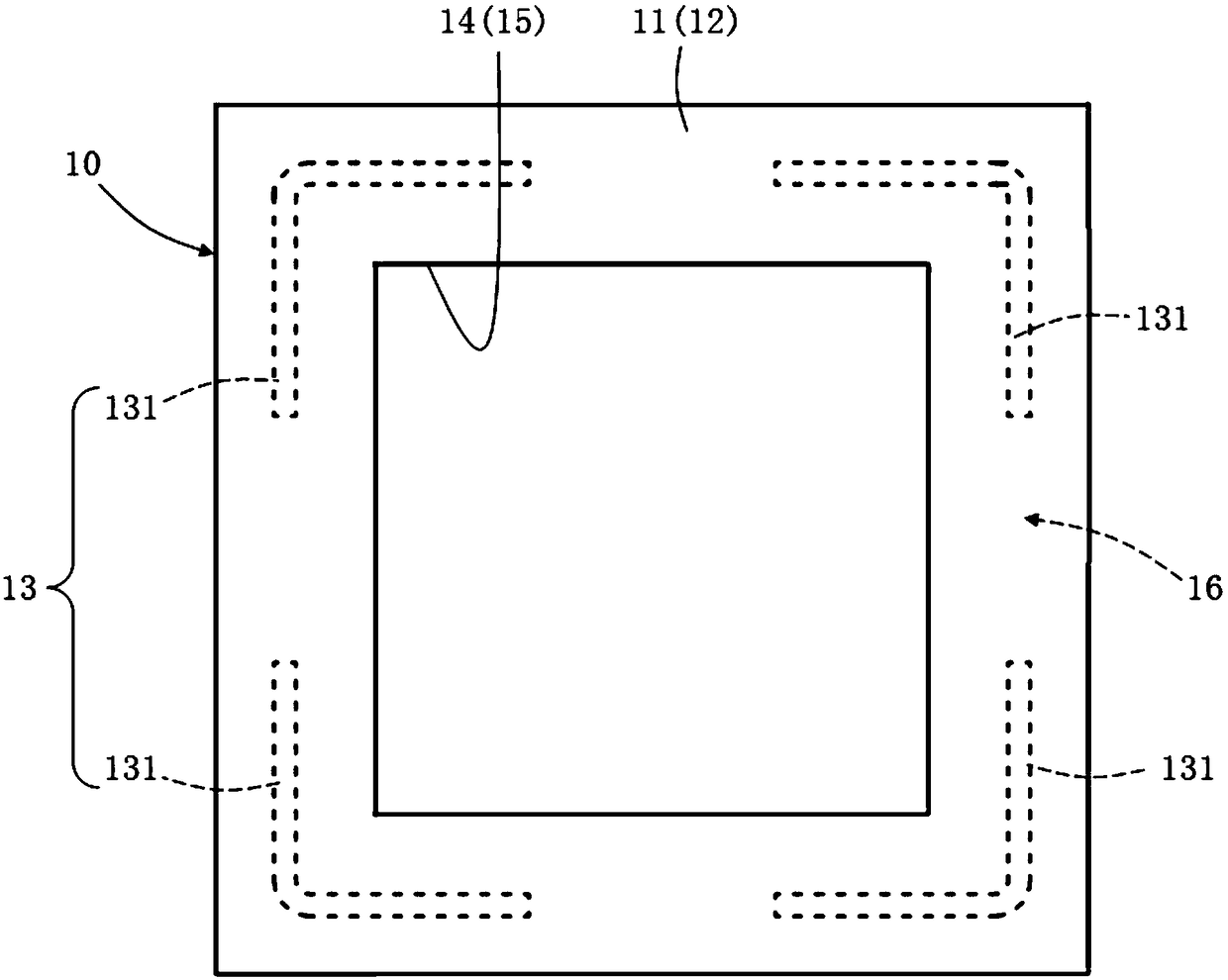
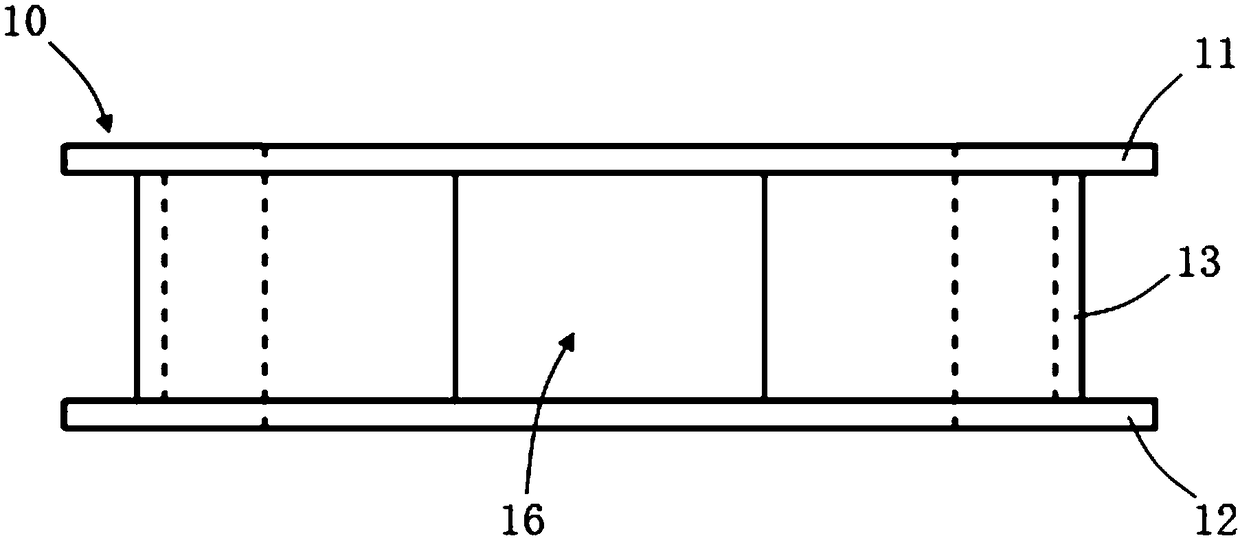
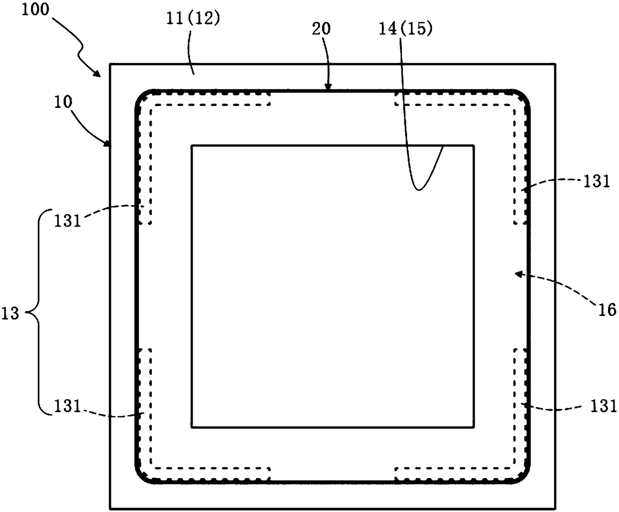
[0048] A magnetic field generating device, which includes a transmitting coil and such as Figure 5 , Figure 6 Magnetic Matt material integration 200 shown. in:

[0049] The transmitting coil is formed by winding a litz wire with a specification of 0.1×200 strands; the transmitting coil is shaped as a single-turn square coil, and the first and last ends of the metal wire are connected to a radio frequency coaxial connector (BNC) with an impedance of 50 ohms. -KFD) welding; the square plate seat of the radio frequency coaxial connector can be welded to the female head.

[0050] In Example 1, the litz wire of the transmitting coil is a polyester silk-covered wire with polyurethane enameled wire as the core wire; the geometric parameters of the litz wire of the transmitting coil are as follows: the outer diameter of the litz wire is about 1.92mm, and each The cross-sectional area of ​​the r...

Embodiment 2

[0057] Embodiment 2: A wireless power transmission system including the magnetic field generating device in Embodiment 1.

[0058] The wireless power transmission system includes the magnetic field generating device of Embodiment 1 and a power pick-up coil. The preparation step of the electric energy pickup coil includes: winding 3 turns with 0.1×50 Litz wire to form a ring with a diameter of about 4 cm. Wherein, the Litz wire of the electric energy pick-up coil is a polyester silk-covered wire with a polyurethane enameled wire as a core wire.

[0059] Such as Figure 7 As shown, it shows the vertical component magnetic field distribution diagram of the integrated surface of the magnetite material measured by the present invention at a working frequency of 85KHz. Figure 7 By connecting the transmitting coil to the Port 1 port of the Keysight E5071C network analyzer, connecting the power pick-up coil to the Port 2 port, and scanning 12×12 grid points within the range of 480m...


PUM

PropertyMeasurementUnit
Lengthaaaaaaaaaa
Widthaaaaaaaaaa
Thicknessaaaaaaaaaa

Abstract

The invention provides a magnetic field generation device based on a magnetic metamaterial and a wireless electric energy transmission system. The magnetic field generation device mainly consists of an energy emitting end and a magnetic metamaterial assembly, wherein the magnetic metamaterial assembly is loaded onto the energy emitting end and has the sub-wavelength characteristic; the magnetic metamaterial assembly comprises a plurality of magnetic metamaterial units. The magnetic field generation device has the advantages that the magnetic metamaterial unit of which the frequency tuning range is controlled within the kilohertz frequency band is excited by an emitting coil, so that each magnetic metamaterial unit can be coupled by a magnetic field to form a special channel band; the different magnetic field distribution can be correspondingly excited at different frequency points within the channel band, so that a magnetic field which is relatively uniformly distributed in a large area can be obtained through regulating and controlling the frequency, thereby realizing the magnetic field generation device capable of performing wireless electric energy transmission with multiple targets, and the wireless electric energy transmission containing the magnetic field generation device.

Description

technical field [0001] The present invention relates to the technical field of magnetic field resonance coupled wireless power transmission, in particular to a magnetic field generating device and a wireless power transmission system based on magnetite materials. Background technique [0002] Wireless Power Transfer (WPT) is to convert electrical energy into other forms of relay energy through the transmitter, such as electromagnetic field energy, laser, microwave and mechanical waves, etc., after a certain distance is transmitted through the air, and then relayed through the receiver The energy is converted into electrical energy to realize wireless transmission of electrical energy. According to the different forms of relay energy in the process of energy transmission, it can be divided into magnetic (field) coupling, electric (field) coupling, electromagnetic radiation and mechanical wave coupling (ultrasonic coupling). Due to the large transmission power and high effici...

Claims


Application Information

Patent Timeline
IPC IPC(8): H02J50/12H02J50/20H01F38/14H01F5/00
CPCH01F5/00H01F38/14H02J50/12H02J50/20
Inventor 李云辉曾超李果王宇倩郭桂春余维健方恺陈宇光张冶文陈鸿
Owner TONGJI UNIV
Why Eureka
Eureka Blog
Learn More