Micro optical probe

An optical probe, miniature technology, applied in optics, optical components, medical science, etc., can solve the problems of heavy weight, inability to apply clinically, and large volume, and achieve the effect of light weight, optimized internal structure, and small volume

Pending Publication Date: 2018-07-10
苏州溢博伦光电仪器有限公司
View PDF6 Cites 5 Cited by
  • Summary
  • Abstract
  • Description
  • Claims
  • Application Information

AI Technical Summary

Problems solved by technology

[0007] Aiming at the technical problems that the existing miniature probes are too heavy and

Method used


Image

  • Micro optical probe
  • Micro optical probe
  • Micro optical probe

Examples


Embodiment Construction

[0043] Further detailed explanation through specific implementation mode below:

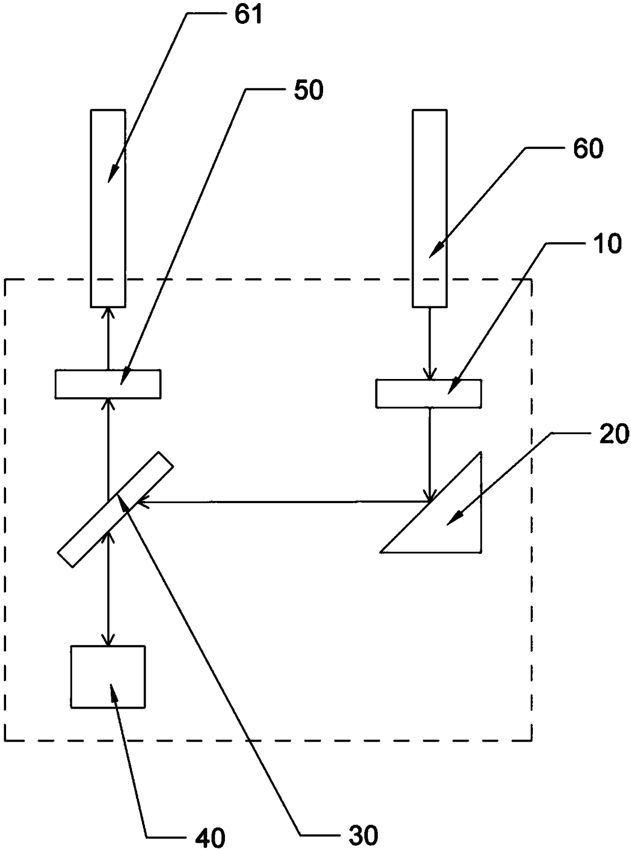
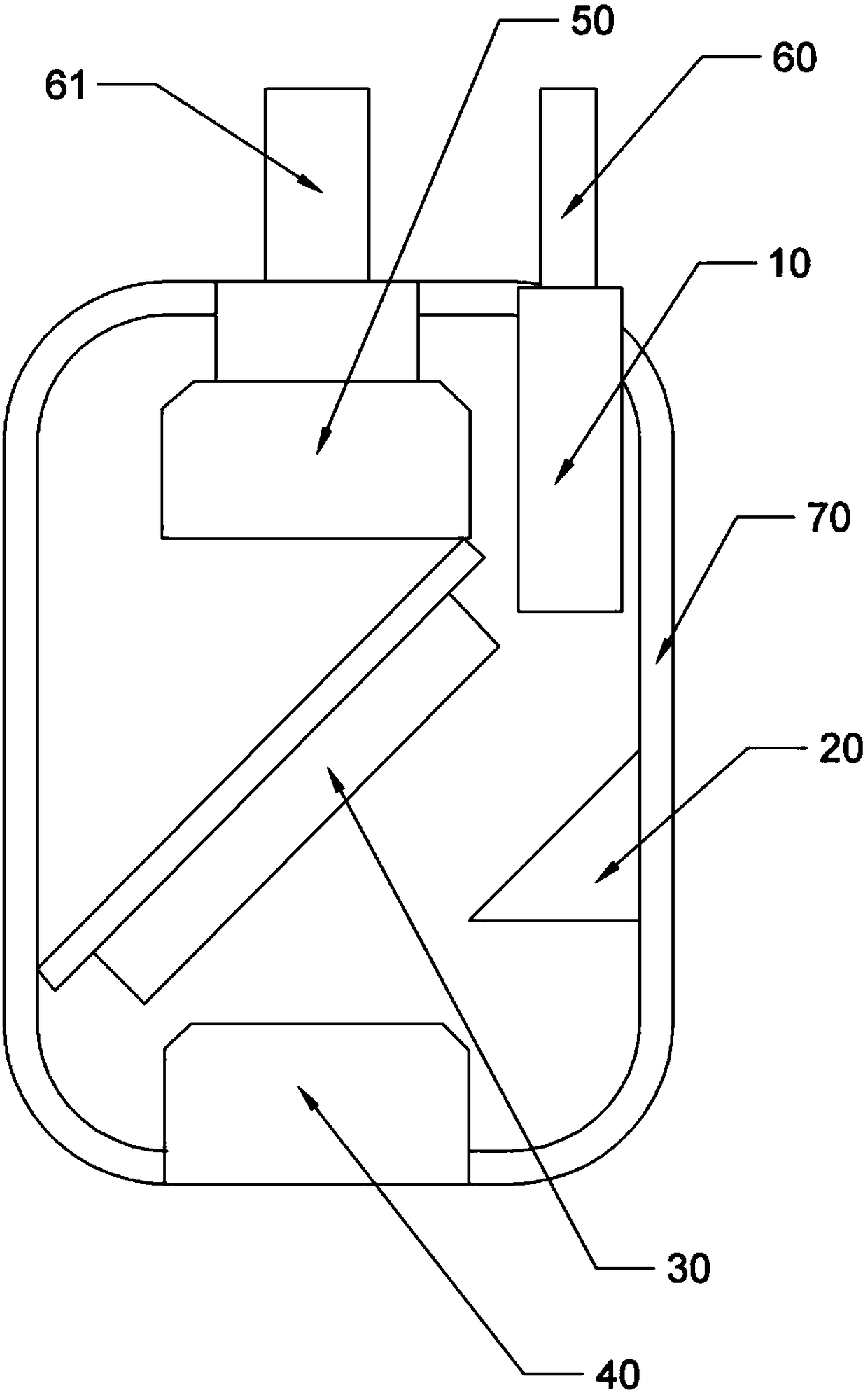
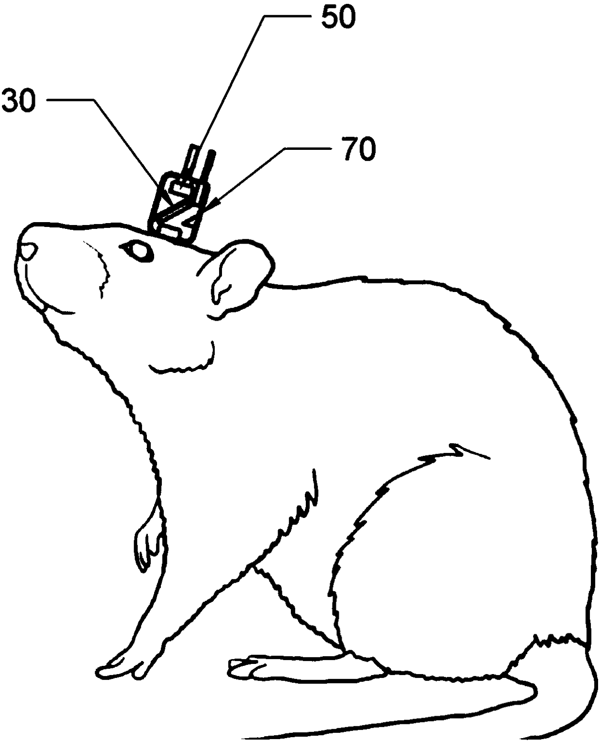
[0044] The reference numerals in the accompanying drawings include: collimating lens 10, reflector 20, dichroic mirror scanner 30, objective lens 40, focusing lens 50, laser input optical fiber 60, laser output optical fiber 61, housing 70, substrate 11 , driver 22, dichroic mirror 33.

[0045] The embodiment is basically as attached figure 1 , figure 2 Shown: micro-optical probe, according to optical path comprises: collimating lens 10, mirror 20, dichroic mirror scanner 30, objective lens 40 and focusing lens 50, objective lens 40 is an aspherical lens, collimating lens 10 is used for collimating Directly output the laser light from the laser input fiber 60 and reduce the chromatic aberration between different frequency lasers and output the laser signal to the reflector 20 . The radius of curvature of the objective lens 40 of the aspheric lens changes along with the central axis, so as to ...


PUM


Abstract

The invention relates to the technical field of optical imaging. The invention provides a micro optical probe for solving technical problems such as that the existing micro-probe is overweight, oversized and cannot be used in clinical. The micro optical probe comprises a focusing lens for collecting nonlinear optics signals; a collimating lens for collimating laser light output by a laser input fiber and reducing chromatic aberration between lasers of different frequencies and outputting laser signals; a dichroic mirror scanner for separating the laser and the nonlinear optical signals and outputting the nonlinear optics signals, and for changing the angle of incidence of the laser to cause the laser to perform two-dimensional scanning on the plane of the internal tissue of living samples;an objective lens for concentrating laser light from the dichroic mirror scanner into a living body sample to excite the living sample to produce a nonlinear optical signal and for outputting a nonlinear optical signal.

Description

technical field [0001] The invention relates to the technical field of optical imaging, in particular to a miniature optical probe. Background technique [0002] To study the fundamentals of subcellular, cellular, circuit, and higher-level neuronal information processing in freely moving animals, photon microscopy is commonly employed as a technique for noninvasive optical brain imaging. In general, when using a bench-top two-photon microscope, the head of the living specimen (animal under study) needs to be fixed at all times, and the living specimen is always under physical restraint and emotional stress (fear, unknown) during the experiment. The behavior of living specimens in free-moving situations cannot be effectively studied. [0003] In order to solve the above problems, the Chinese Patent Publication No. CN107049247A discloses a miniature two-photon microscopic imaging device and method, and a living sample behavioral imaging system. The miniature two-photon micros...

Claims


Application Information

Patent Timeline
IPC IPC(8): A61B5/00G02B23/24
CPCA61B5/0062A61B5/0082G02B23/2407G02B23/2469
Inventor 不公告发明人
Owner 苏州溢博伦光电仪器有限公司
Why Eureka
Try Eureka