Novel pneumatic stirring catalytic distillation device

A catalytic rectification and pneumatic technology, applied in fractional distillation, chemical industry, distillation and separation, etc., can solve problems such as uneven mixing of gas-liquid-solid three-phase

Active Publication Date: 2018-07-10
SINOPEC SHANGHAI ENG +1
View PDF7 Cites 3 Cited by
  • Summary
  • Abstract
  • Description
  • Claims
  • Application Information

AI Technical Summary

Problems solved by technology

[0008] The technical problem to be solved by the present invention is the problem of uneven gas-liquid-solid three-phase mixing between the tray

Method used


Image

  • Novel pneumatic stirring catalytic distillation device
  • Novel pneumatic stirring catalytic distillation device

Examples


Embodiment 1

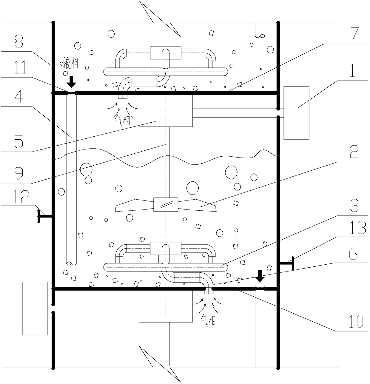
[0023] A new type of pneumatic stirring catalytic rectification device, such as figure 1 As shown, the reactor tray structure mainly includes: pneumatic agitator 1, paddle 2, gas distributor 3, downcomer 4, gear box 5, air riser 6, tray 7, shell 8, shaft 9, Tray 10, filter screen 11, catalyst replenishment port 12, catalyst outlet 13.

[0024] The light component enters the reactor from the lower tray of the reactor, and the heavy component enters the reactor from the upper tray of the reactor. A certain amount of solid particles or particulate catalysts are placed on each tray, and the reaction liquid phase from the upper tray 7 enters the space between the two trays through the downcomer 4 . The reaction gas phase from the adjacent lower tray of the tray 10 enters the space of the two trays through the gas riser 6, and is uniformly sprayed into the liquid-solid mixture of the tray 10 through the gas distributor 3 in the form of bubbles. The pneumatic agitator 1 installed o...

Embodiment 2

[0031] According to the conditions and steps described in Example 1, the distance between two adjacent trays is H, the inner diameter of the tower is D, H is 300 mm, D is 200 mm, and the gas distributor is a double-ring gas distributor. The ratio of the outer pipe diameter a of the double-ring gas distributor to the inner diameter D of the tower is 0.3, the ratio of the inner pipe diameter b to the inner diameter D of the tower is 0.2, and the center of the double-ring gas distributor coincides with the center of the tray. The opening diameter of the outer tube of the gas distributor is 2mm, the opening diameter of the inner tube is 1mm, and the openings are equally spaced and evenly distributed. The ratio of the diameter c of the riser to the inner diameter D of the tower is 0.05, the distance between the center of the inlet of the riser and the center of the tray is 0.1D, the ratio of the diameter d of the downcomer to the inner diameter D of the tower is 0.08, and the center...

Embodiment 3

[0034] According to the conditions and steps described in Example 1, the distance between two adjacent trays is H, the inner diameter of the tower is D, H is 400 mm, D is 200 mm, and the gas distributor is a double-ring gas distributor. The ratio of the outer pipe diameter a of the double-ring gas distributor to the inner diameter D of the tower is 0.5, the ratio of the inner pipe diameter b to the inner diameter D of the tower is 0.4, and the center of the double-ring gas distributor coincides with the center of the tray. The opening diameter of the outer tube of the gas distributor is 10mm, the opening diameter of the inner tube is 8mm, and the openings are equally spaced and evenly distributed. The ratio of the diameter c of the riser to the inner diameter D of the tower is 0.1, the distance between the center of the inlet of the riser and the center of the tray is 0.2D, the ratio of the diameter d of the downcomer to the inner diameter D of the tower is 0.25, and the center...


PUM


Abstract

The invention relates to a novel pneumatic stirring catalytic distillation device. The distillation device mainly solves the problem that the gas, liquid and solid phases between tower plates in the catalytic rectification tower cannot be uniformly mixed. According to the novel pneumatic stirring catalytic distillation device, each tower plate separately utilizes a pneumatic stirrer in the side, astirring paddle is suspended on the top of the tower plate in the form of top suspension, each tower plate is provided with a riser pipe and a downcomer, a gas inlet of the riser pipe is arranged inone side of each tower plate without a pneumatic pump, the upper part of the riser pipe is connected to a gas distributor, gas in the lower tower plate is uniformly sprayed into a liquid-solid mixtureon the tower plate through the gas distributor, the upper part of the downcomer is provided with a filter net for preventing a particle or microsphere catalyst from falling into the lower tower plate, and the lower part of the downcomer is arranged at the lower part of the tower plate. The device extending below the liquid levels of the adjacent lower plates well solves the above problem and canbe used in a catalytic distillation tower.

Description

technical field [0001] The invention relates to a novel pneumatic stirring catalytic rectification device. technical background [0002] With the rise and development of green chemical industry, chemical process intensification technology has attracted more and more attention. Reactive distillation technology, which integrates chemical reaction and rectification separation to form a multifunctional reaction device, is one of the ways to achieve chemical process intensification. Catalytic distillation is a heterogeneous catalytic reaction distillation technology developed on the basis of homogeneous reaction distillation. In this technology, solid catalysts are placed on each layer of trays in the reaction section of the tower, and the gas and liquid go up and down respectively. Countercurrent flow, chemical reaction and rectification separation are highly coupled in the tower, the reaction product can be continuously removed, and the heat of reaction can also be used as the...

Claims


Application Information

Patent Timeline
IPC IPC(8): B01D3/00B01D3/32B01J8/02C07C67/03C07C69/14
CPCB01D3/009B01D3/32B01J8/0292C07C67/03Y02P20/10
Inventor 刘肖肖江继峰陈迎裴凯凯徐曼张艺张翼
Owner SINOPEC SHANGHAI ENG
Why Eureka
Try Eureka