Curved bridge fitting laying structure based on orthogonal prefabricated beam plate and laying method thereof

A technology of curved bridges and prefabricated girders, applied in the field of bridge structures, can solve the problems of complex internal force distribution of transverse bridge slabs, affect the continuity of bridge decks between spans, increase the complexity of assembly construction, etc., achieve reasonable and ingenious layout methods, and simplify design calculations , the effect of shortening the construction period

Pending Publication Date: 2018-07-10
LUOYANG INST OF SCI & TECH
View PDF8 Cites 1 Cited by
  • Summary
  • Abstract
  • Description
  • Claims
  • Application Information

AI Technical Summary

Problems solved by technology

The disadvantages of cast-in-place curved girder bridges are obvious: it is necessary to build a full house of supports, which consumes a lot of formwork and has a long construction period. For bridges with high piers in mountainous areas and municipal bridges with large traffic flow under the bridge, cast-in-place support has great limitations.
The prefabricated and assembled special-shaped slab method, although the construction period is shorter than that of cast-in-place beams, has obvious disadvantages: the slope of each span of prefabricated beams is different, especially the inner and outer side beams of the side spans are irregular special-shaped beams and slabs, and non-standard special-shaped prefabricated beams and slabs are affected. The complex force and structural design also increase the complexity of assembly construction, and at the same time affect the continuity of the bridge deck between spans, making the internal force distribution of the cross bridge to each girder slab more complicated

Method used


Image

  • Curved bridge fitting laying structure based on orthogonal prefabricated beam plate and laying method thereof
  • Curved bridge fitting laying structure based on orthogonal prefabricated beam plate and laying method thereof
  • Curved bridge fitting laying structure based on orthogonal prefabricated beam plate and laying method thereof

Examples


Embodiment Construction

[0034] The embodiments of the present invention will be described in detail below in conjunction with the accompanying drawings. This embodiment is based on the technical solution of the present invention, and provides detailed implementation methods and specific operating procedures, but the scope of protection of the present invention is not limited to the following embodiments. .

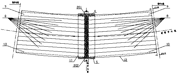
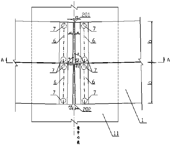
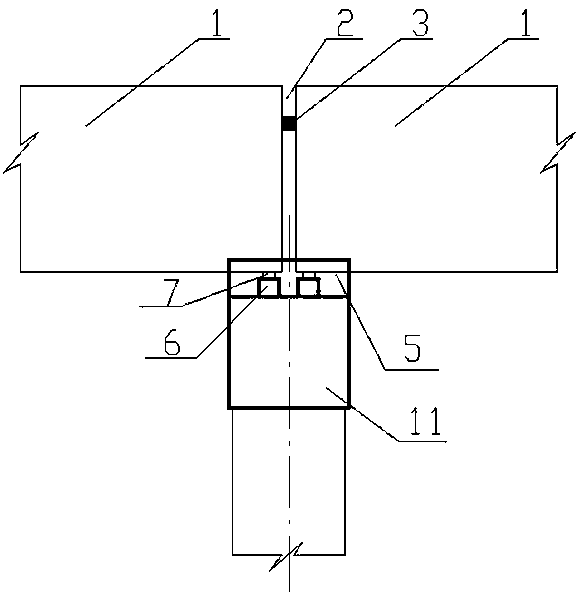
[0035] Explanation of parameters of the present invention: In the present invention, n is the number of bridge piers; m is the number of girder slabs in each span; R is the radius of the curved bridge; L0 is the reference span length of the orthogonal prefabricated girder slab 1; α is the center line of the slab The angle between the direction (tangential to the chord) and the centerline of the cap beam (radial), see figure 2 ; b is the width of the orthogonal prefabricated beam slab 1; f1 is the width of the inner plate seam 201; f2 is the width of the outer plate joint 202.

[0036]The curved...


PUM


Abstract

Provided is a curved bridge fitting laying structure based on orthogonal prefabricated beam plates and a laying method thereof. The fitting laying structure includes an upper portion beam plate system, a beam plate protection structure and a lower portion support structure. The upper portion beam plate system comprises a plurality of spans of the beam plates arranged in the curve chord tangent direction of the curve, and each of the beam plates is the same in size, and each of the beam plates comprises the orthogonal prefabricated beam plates arranged side by side. Plate seams of every span formed by each of the orthogonal prefabricated beam plate are trapezoidal staggered, and the plate seams are filled with wedge-shaped wood strips. The laying method includes the determination of a benchmark span, the laying of pier capping beams, cushion rock and support seats, the laying of middle beams and cantilever side beams, and the laying of the filling of the plate seams and shielding structures of the plate beams. The curved bridge fitting laying structure based on the orthogonal prefabricated beam plates and the laying method thereof are applicable to a curved bridge with assembly typeconstruction on an upper portion of the curved bridge, and prefabricated beam plates of each span of the curved bridge are the same in size, the plate seams between each span are regularly staggered,the laying method is reasonable and ingenious, and the calculation of the design of the beam plates is simplified, the construction quality of the prefabricated beams is ensured, and the assembly construction can shorten the construction period of the curved beam bridge.

Description

technical field [0001] The invention relates to the technical field of bridge structures, in particular to a curved bridge fitting layout structure and a layout method based on orthogonal prefabricated girder slabs. Background technique [0002] When the bridge site is located in the curved section of the road, considering the smooth and comfortable alignment of the entire road, in order to ensure that the route index meets the design service level, it is necessary to build a curved bridge consistent with the direction and curvature of the route. At present, designers usually adopt the method of casting curved girder bridges on site, or prefabricating and assembling special-shaped slabs to fit the inner and outer curves. The disadvantages of cast-in-place curved girder bridges are obvious: it is necessary to build a full house of supports, which consumes a lot of formwork and has a long construction period. For bridges with high piers in mountainous areas and municipal bridg...

Claims


Application Information

Patent Timeline
Patent Type & Authority Applications(China)
IPC IPC(8): E01D21/00
CPCE01D21/00
Inventor 董晓梅苗振旭何朋立贾晓敏李华然童怀峰何国柱何怡
Owner LUOYANG INST OF SCI & TECH
Why Eureka
Try Eureka