Precise temperature-controlled liquid reservoir for mechanical pump driving two-phase fluid circuit and assembly method

A fluid circuit and liquid storage technology, which is applied in the field of precision temperature-controlled liquid storage and assembly of two-phase fluid circuits driven by mechanical pumps. problems, to achieve the effects of improved structural mechanical properties, high cooling capacity utilization, and direct heat transfer methods

Active Publication Date: 2020-09-18
BEIJING RES INST OF SPATIAL MECHANICAL & ELECTRICAL TECH
View PDF8 Cites 0 Cited by
  • Summary
  • Abstract
  • Description
  • Claims
  • Application Information

AI Technical Summary

Problems solved by technology

This cooling method has disadvantages such as large input power consumption, low cooling efficiency, low cooling capacity utilization rate, and the need for control circuit regulation, which makes the structure of the liquid receiver more complicated, which greatly reduces the reliability of the system, and the semiconductor refrigeration sheet cooling at the same time A lot of waste heat will be generated, and other cooling capacity is still needed for cooling
At the same time, the internal structure of the liquid reservoir adopts a wire mesh structure to realize the management function of the working medium flow state under microgravity. The wire mesh has low strength, is easy to break, and is difficult to assemble and fix.

Method used


Image

  • Precise temperature-controlled liquid reservoir for mechanical pump driving two-phase fluid circuit and assembly method
  • Precise temperature-controlled liquid reservoir for mechanical pump driving two-phase fluid circuit and assembly method
  • Precise temperature-controlled liquid reservoir for mechanical pump driving two-phase fluid circuit and assembly method

Examples


Embodiment Construction

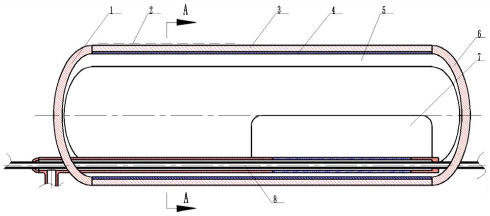
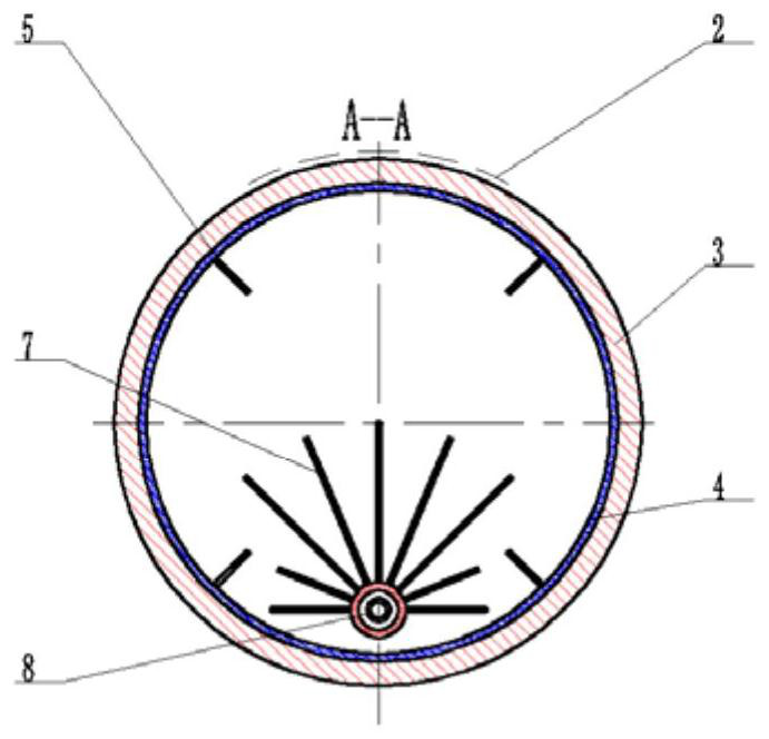
[0033] Aiming at the deficiencies of the prior art, the present invention proposes a precision temperature-controlled liquid storage device for a two-phase fluid circuit driven by a mechanical pump, including a left end head 1, a heating device 2, a cylinder body 3, and a capillary structure lining the cylinder body 4. Flow guiding device 5, right end head 6, liquid collector 7 and passive cooling capillary drain 8.

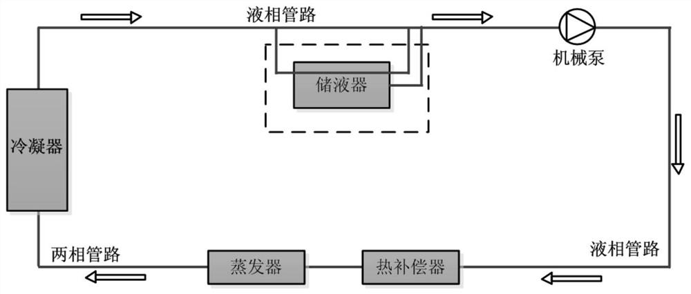
[0034] Such as figure 1 The schematic diagram of the two-phase temperature-controlled fluid circuit driven by a mechanical pump is shown. The left end head 1, the cylinder body 3, and the right end head 6 are connected by welding to form the liquid storage shell. The surface is bonded by welding, the heating device 2 is pasted on the outer wall of the cylinder, the flow guide device 5 is a perforated metal plate, fixed on the inner surface of the shell and distributed radially, and the passive cooling capillary drain structure 8 includes an outer sleeve Drain en...


PUM


Abstract

The invention discloses a precision temperature control type reservoir and method for a mechanical pump to drive a two-phase fluid loop. The reservoir comprises a reservoir shell, a heating device, afluid collector and a passive cooling capillary drain pipe. The fluid collector is located on the inner surface of the reservoir shell. The heating device is located on the outer side of the reservoirshell. The passive cooling capillary drain pipe structure penetrates through the reservoir shell and communicates with an external fluid loop system. When the fluid to be cooled passes through the reservoir, the fluid is sent, by the fluid collector, to the passive cooling capillary drain pipe to be cooled. According to the precision temperature control type reservoir and method for the mechanical pump to drive the two-phase fluid loop, the interior of the reservoir is cooled by adopting the heat exchange manner, the temperature control function is realized only by regulating the heating power consumption, and therefore the structure of the reservoir is remarkably simplified; meanwhile, the drain pipe can partially keep the relative cool state all the time, it is effectively avoided thatbubbles exist near the drain pipe, and it is guaranteed that the reservoir drains out the fluid phase working medium; and because the sheet metal structure is adopted for the fluid collector and a flow guiding device of the reservoir, the structural mechanical property can be obviously improved.

Description

technical field [0001] The invention relates to the field of aerospace thermal control, in particular to a precision temperature-controlled liquid reservoir and an assembly method for a mechanical pump driving a two-phase fluid circuit. Background technique [0002] In recent years, with the development of aerospace technology, the requirements for aerospace thermal control technology are getting higher and higher. Mechanical pump driven two-phase fluid loop technology (MPTL), as an active temperature control system, has gradually become a research hotspot in the field of aerospace thermal control. The MPTL system is mainly composed of liquid receiver, mechanical pump, preheater, evaporator, condenser and connecting pipelines, as shown in the attached figure 1 shown. Its working principle is to use a mechanical pump to drive the circulation of the working fluid in the loop system: the supercooled working fluid first flows through the preheater, is heated to a saturated sta...

Claims


Application Information

Patent Timeline
Patent Type & Authority Patents(China)
IPC IPC(8): F25B43/00F25B49/00
CPCF25B43/00F25B49/00
Inventor 赵振明张焕冬孟庆亮于峰杨涛夏晨晖赵宇赵石磊高腾魏强邵何强
Owner BEIJING RES INST OF SPATIAL MECHANICAL & ELECTRICAL TECH
Why Eureka
Try Eureka