Semi-solid slurry preparation and forming integrated equipment

A semi-solid slurry and equipment technology, applied in the field of semi-solid slurry preparation and molding integrated equipment, can solve the problems of inability to meet industrial production requirements, personal safety threats, long time consumption, etc., to save manpower and production time, The effect of shortening the molding process and reducing the energy consumption of preparation

Active Publication Date: 2018-07-13
KUNMING UNIV OF SCI & TECH
View PDF7 Cites 8 Cited by
  • Summary
  • Abstract
  • Description
  • Claims
  • Application Information

AI Technical Summary

Problems solved by technology

The preparation process of semi-solid alloys includes smelting, pulping and forming. The molten metal after smelting needs to be nucleated and then manually transferred to the forming equipment. Threat, can not meet the production requirements of the industry
For the nucleation process, commonly used methods include mechanical stirring method, electromagnetic stirring method and inclined plate cooling method, etc., but there are obvious deficiencies in all of them.
For example, the mechanical stirring and electromagnetic stirring equipment are huge, the investment is high, and the energy consumption is large, resulting in high preparation costs; and the inclined plate is easy to stick to the alloy melt, which needs to be cleaned continuously, which wastes the alloy

Method used


Image

  • Semi-solid slurry preparation and forming integrated equipment
  • Semi-solid slurry preparation and forming integrated equipment
  • Semi-solid slurry preparation and forming integrated equipment

Examples


Embodiment 1

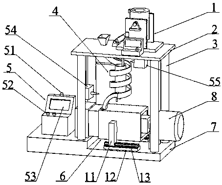
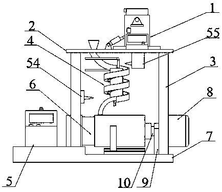
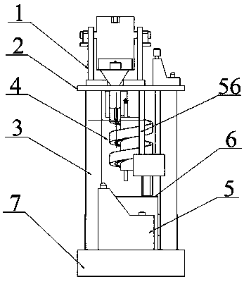
[0035] Embodiment 1: as Figure 1~9 As shown, an integrated equipment for semi-solid slurry preparation and molding, including a melting device 1, a top plate 2, a support column 3, a pulping device 4, a numerical control console 5, an extrusion molding device 6, a base 7, and a numerical control console 5 is set on the base 7, the support column 3 is vertically set on the base 7 and is located on the side of the numerical control console 5, the top plate 2 is horizontally set on the top of the support column 3, the melting device 1 is set on the top plate 2, and the extrusion molding device 6 Set on the base 7 and below the top plate 2, the pulping device 4 is set on the lower end of the top plate 2 and above the extruding device 6, the smelting device 1, the pulping device 4, and the extruding device 6 are connected in sequence and are respectively connected with the numerical control operation Station 5 connection;

[0036] The smelting device 1 includes a melting furnace ...

Embodiment 2

[0053] Embodiment 2: The structure of the semi-solid slurry preparation and molding integrated equipment in this embodiment is basically the same as the structure of the semi-solid slurry preparation and molding integrated equipment in Example 1. The difference is that the annular flow channel 29 in this embodiment The included angle with the horizontal direction is 60°, and the width of the annular flow channel 29 is 5 cm.

Embodiment 3

[0054] Embodiment 3: The structure of the semi-solid slurry preparation and molding integrated equipment in this embodiment is basically the same as the structure of the semi-solid slurry preparation and molding integrated equipment in Example 1. The difference is that the annular flow channel 29 in this embodiment The included angle with the horizontal direction is 45°, and the width of the annular flow channel 29 is 4cm.


PUM


Abstract

The invention relates to semi-solid slurry preparation and forming integrated equipment, and belongs to the technical field of material processing. The equipment comprises a smelting device, a top plate, a supporting column, a slurry preparing device, a numerical control operation table, an extruding forming device and a base; the numerical control operation table is arranged on the base; the supporting column is arranged on the base and located on one side of the numerical control operation table; the top plate is horizontally arranged at the top end of the supporting column; the smelting device is arranged on the top plate; the extruding forming device is arranged on the base and located below the top plate; the pulp preparing device is arranged at the lower end of the top plate and located above the extruding forming device; and the smelting device, the slurry preparing device and the extruding forming device are sequentially communicated and are correspondingly connected with the numerical control operation table.

Description

technical field [0001] The invention relates to an integrated equipment for semi-solid slurry preparation and molding, which belongs to the technical field of material processing equipment. Background technique [0002] Semi-solid molding technology, referred to as SSM, has received extensive attention and in-depth research since it was pioneered by Professor M.C.Flemings of the Massachusetts Institute of Technology in the early 1970s. Compared with traditional casting, semi-solid molding technology has a certain volume fraction of solid phase in its liquid phase, which has small latent heat of crystallization and small solidification shrinkage. Therefore, the formed parts have compact structure, high mechanical properties, high dimensional accuracy, can realize near-final molding, have little thermal impact on the mold, and can improve the service life of the mold. Compared with traditional forging, it contains a certain amount of liquid phase, has small deformation resist...

Claims


Application Information

Patent Timeline
Patent Type & Authority Applications(China)
IPC IPC(8): B22D17/00C22C1/00B22D1/00C22C1/03
CPCC22C1/026C22C1/03B22D1/007B22D17/007C22C1/12
Inventor 李璐王秋平周荣锋
Owner KUNMING UNIV OF SCI & TECH
Why Eureka
Try Eureka