A gas adsorbent evaluation device
A gas adsorbent and evaluation device technology, applied in the direction of using substance absorption and weighing, etc., can solve the problems of unable to test the adsorbent and the limitation of the adsorbent form, etc., and achieve the effect of clear operation process, convenient operation and good air tightness
- Summary
- Abstract
- Description
- Claims
- Application Information
AI Technical Summary
Problems solved by technology
Method used
Image

Examples
Embodiment 1
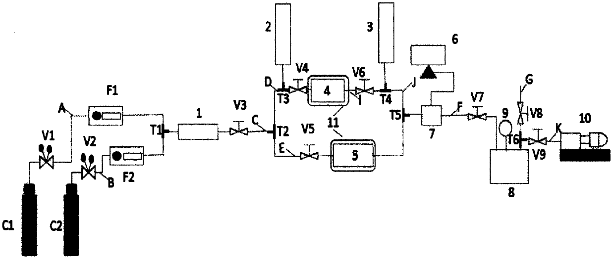
[0050] Take an appropriate amount of spherical cellulose airgel in the cylindrical adsorption bed 4, and after checking the airtightness of the device, turn on the vacuum pump 10 to vacuum the cylindrical adsorption bed 4, and then close all valves and vacuum pumps for testing.
[0051] According to the mixed gas composition N 2 The concentration is C 1 and CO 2 for C 2 For testing, open the first pressure reducing valve V1, the second pressure reducing valve V2, the first needle valve V3, the third V5, and the sixth needle valve V8, and then adjust the first mass flow meter F1, the second mass flow meter F2 makes N 2 The flow rate is l 1 , CO 2 The flow rate is l 2 , then the total flow rate of the mixed gas is l=l 1 +l 2 , when the gas chromatograph 7 shows CO 2 The concentration is C 2 , N 2 The concentration is C 1 And when it is stable, it proves that the system is stable, record the data at this time, and at the same time use the pressure test table 2 and the...
Embodiment 2
[0061] The adsorption performance of cellulose airgel was tested by static method.
[0062] The same method as Example 1 checks the airtightness of the device and evacuates the cylindrical adsorption bed 4, then opens the first needle valve V3, feeds a certain amount of pure carbon dioxide gas into the contrast gas storage tank 5, and then closes the second needle valve V3. One needle valve V3, after the system is stable, write down the reading P of the pressure test gauge 2 at this time 1 and temperature test reading T of Table 3 1 , and then open the second needle valve V4 and the fourth needle valve V6 to test the adsorption performance of the adsorbent by the static method. When the readings of the pressure test gauge and temperature test gauge no longer change, it proves that the adsorbent reaches the maximum amount, that is, the adsorption reaches saturation. Note down the pressure P at this time 2 and temperature T 2 , the experiment ends. Because the gas entering t...
Embodiment 3
[0069] The adsorption properties of spherical cellulose aerogels at different temperatures were detected by dynamic method. Its experimental procedure is substantially identical with embodiment 1. First, the cellulose airgel is loaded into the cylindrical adsorption bed 4 (volume ratio is about 2:3), and the airtightness of the system is detected according to the method of the embodiment. After the airtightness is good, close the second needle valve V4 and the fourth needle valve V6, open the first pressure reducing valve V1 and the second pressure reducing valve V2, and adjust the first mass flow meter F1 and the second mass flow meter F2 to make N 2 and CO 2 The flow rate is l 1 and l 2 , then the total flow rate of the mixed gas is l=l 1 +l 2 . Open the first needle valve V3 to enter the mixed gas into the test system, observe the changes in the readings of the gas chromatograph analyzer 7, when the readings reflect that the gas concentration of each component remains...
PUM
 Abstract
Description
Claims
Application Information
 - R&D
- Intellectual Property
- Life Sciences
- Materials
- Tech Scout
- Unparalleled Data Quality
- Higher Quality Content
- 60% Fewer Hallucinations
Browse by: Latest US Patents, China's latest patents, Technical Efficacy Thesaurus, Application Domain, Technology Topic, Popular Technical Reports.
© 2025 PatSnap. All rights reserved.Legal|Privacy policy|Modern Slavery Act Transparency Statement|Sitemap|About US| Contact US: help@patsnap.com