Liquid antenna for controlling transmitting-receiving wave beam directions by gravity

A beam direction and antenna technology, applied in the directions of antennas, resonant antennas, antenna components, etc., can solve the problem of high cost and achieve the advantages of compactness and simplicity.

Pending Publication Date: 2018-07-13
太行通信股份有限公司
View PDF9 Cites 23 Cited by
  • Summary
  • Abstract
  • Description
  • Claims
  • Application Information

AI Technical Summary

Problems solved by technology

Obviously, the function of the traditional electron beam steering antenna system requires a complex and huge controller, detector and phase shifting circuit to be realized

Method used


Image

  • Liquid antenna for controlling transmitting-receiving wave beam directions by gravity
  • Liquid antenna for controlling transmitting-receiving wave beam directions by gravity
  • Liquid antenna for controlling transmitting-receiving wave beam directions by gravity

Examples


Embodiment 1

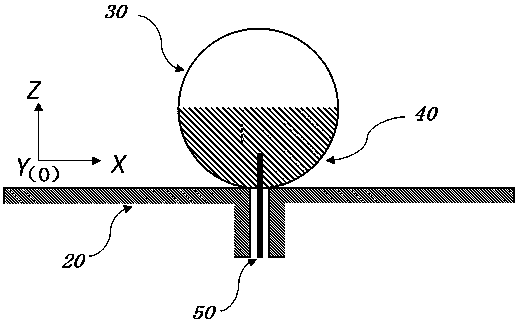
[0055] Such as figure 1 As shown, this embodiment is a liquid antenna for directional emission and reception of horizontal beam signals, which is a spherical liquid antenna, including fluid, a spherical thin-walled container 30, and a grounding layer 20 (also a conductive plate). The container, the ground layer 20, the feeding structure of the antenna, and the carrier of the antenna are fixedly connected. The container 30 has a closed spherical inner cavity and a spherical outer contour, and the inner cavity of the container 30 is partially filled with fluid (the volume of the fluid accounts for 50% to 70% of the inner cavity volume, preferably 65% ​​in this embodiment), the fluid All are composed of the first liquid 40 (the fluid can also contain multiple liquids, this embodiment is a simplified model, preferably one), there is a space above the container that is not filled by the fluid, and the interface between the space and the fluid is always kept horizontal At the liqui...

Embodiment 2

[0063] This embodiment is a liquid antenna for directional emission and reception of vertical beam signals, which is a cylindrical liquid antenna, such as Figure 6 As shown, a thin-walled cylindrical container 30 is included, and the closed cavity of the container 30 is a fluid composed of a first liquid 40 and a second liquid 60 with different relative permittivity and different densities and are incompatible with each other (this embodiment The fluid of the example should contain more than two kinds of liquids with different densities and are incompatible with each other. Among these liquids, the liquid with a lower density should have a larger relative permittivity. To simplify the model, preferably, the fluid of this example is only consists of two liquids), a conductive plate is fixed on the side of the container 30, the conductive plate is fixedly connected to the feed structure, and the conductive plate acts as the ground layer 20 of the antenna to participate in resona...

Embodiment 3

[0075] The beam steering antenna system of this embodiment can be used on satellites 200, 210. The difference from Embodiment 2 is that the density of the first liquid 40 is smaller than that of the second liquid 60, and the relative permittivity of the first liquid 40 is also smaller than that of the second liquid 60. The relative permittivity of the second liquid 60, when the antenna rotates and displaces with the satellite, the radiation lobe of the antenna will tilt to the liquid with a larger relative permittivity that is always kept below, and then through other With the same structural design, it is possible to obtain a liquid antenna whose radiation lobe in the specified frequency band is always vertically downward.

[0076] In addition, the liquid antenna (beam steering antenna system) using gravity to control the pattern in the above embodiments can also communicate with pseudo-satellite systems such as fixed or mobile ground transmitters / receivers, instead of just co...


PUM

PropertyMeasurementUnit
Radiusaaaaaaaaaa
Lengthaaaaaaaaaa
Reflection coefficientaaaaaaaaaa

Abstract

The invention discloses a liquid antenna for controlling transmitting-receiving wave beam directions by gravity, and belongs to the field of communication equipment design and application. The liquidantenna comprises a container with an inner cavity and fluids placed in the inner cavity, the container is fixedly connected with a feed structure of the antenna, the inner cavity is closed, the fluids have spatial steady-state fixed structures formed by constraint of the gravity and the inner cavity, and the wave beam definite direction of the antenna is set by the spatial steady-state fixed structures. The liquid antenna can realize an automatic wave beam turning function without active regulating equipment such as a water pump. When the liquid antenna is used for satellite communication, the liquid antenna has the advantages of capability of covering the broad communication bandwidth of most satellite communication bands (such as GPS), low profile, small size, light weight, conformal property and the like. The liquid antenna is universally applicable to various application scenes such as airplanes, vehicles, body local area networks and IoT (internet of things) requiring suitabilityof the antenna for bearing capacity.

Description

technical field [0001] The invention relates to a liquid antenna with beam automatic steering function, which belongs to the field of communication equipment design and application. Background technique [0002] Phased array (column) antennas with beam steering capabilities have been widely used in commercial and military applications. Generally, this kind of antenna consists of several antenna elements arranged in a specific pattern. With a given differential phase shift value, the electronic phase shifting circuit of this antenna can guide the main radiation lobe to deflect in a specified direction. U.S. Patent US20040008140A1 discloses a method for realizing phase shift by using an electronic phase shift circuit. The electronic phase shift circuit is mainly an analog phase shifter or a digital phase shifter, wherein the analog phase shifter is realized by a single analog control voltage Continuous variation of the phase shift value in the range 0° to 360°. Digital phase...

Claims


Application Information

Patent Timeline
IPC IPC(8): H01Q1/36H01Q1/50H01Q3/02
CPCH01Q1/364H01Q9/30H01Q1/50H01Q3/02
Inventor 黄漪宋朝运
Owner 太行通信股份有限公司
Why Eureka
Try Eureka