
Underwater pipeline dry type automatic welding method and welding device

An automatic welding and underwater pipeline technology, applied in welding equipment, welding accessories, arc welding equipment and other directions, can solve the problems of high labor intensity, low degree of automation, large engineering volume, etc., to improve construction efficiency, ensure welding quality, The effect of improving the feasibility

Pending Publication Date: 2018-07-20
北京隆源自动成型系统有限公司
View PDF9 Cites 26 Cited by
  • Summary
  • Abstract
  • Description
  • Claims
  • Application Information

AI Technical Summary

Problems solved by technology

[0002] With the development of offshore oil and gas resources and the adoption of submarine pipeline transportation, underwater welding construction and underwater equipment and facility welding repair technology have been widely concerned. Exhaust the water for welding, as described in CN102179599B and CN101254563B, use a local hood to exhaust the water in the local hood at the welding place through high-pressure gas, and produce a local dry environment for welding. These underwater welding devices and welding methods either have a large amount of engineering, or It is only suitable for manual work, either with low automation, high labor intensity, or unstable welding quality. This partial mask dry welding method cannot always complete the welding of the entire weld in a dry environment, nor can it achieve The automatic welding along the entire circumference in a dry environment cannot realize the detection and anti-corrosion treatment of the welds in a dry environment. The underwater pipeline dry-type automatic welding device that performs continuous welding, can realize pre-weld treatment and post-weld weld inspection, and can realize post-weld anti-corrosion treatment has great practical significance

Method used


Image

  • Underwater pipeline dry type automatic welding method and welding device
  • Underwater pipeline dry type automatic welding method and welding device
  • Underwater pipeline dry type automatic welding method and welding device

Examples


Embodiment Construction

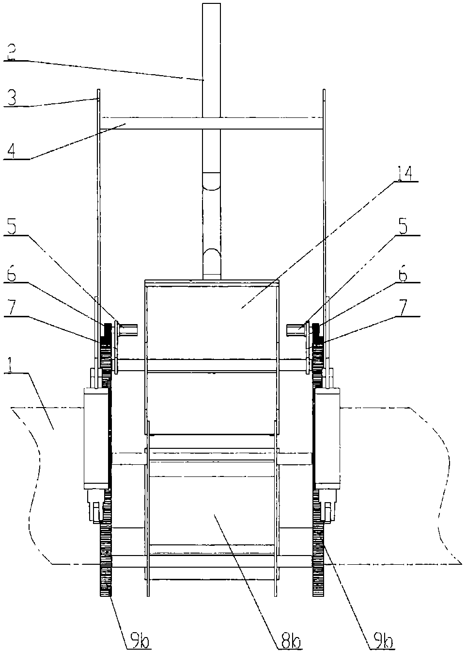
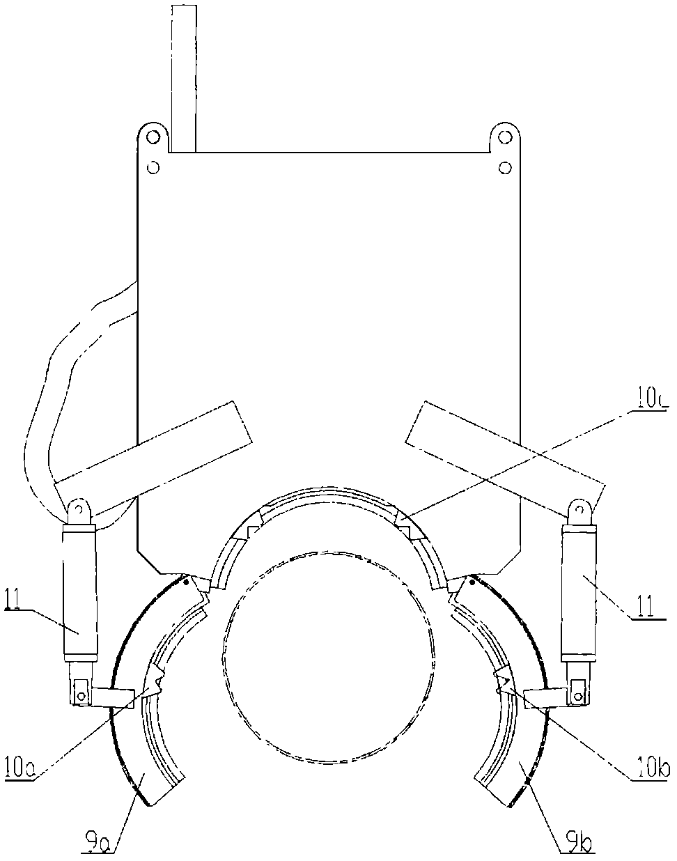
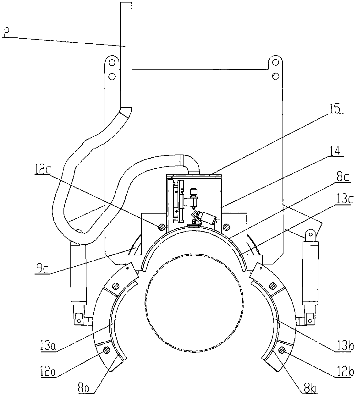
[0044] The underwater dry automatic welding method and welding device can adopt two-lobe clamping and three-lobe clamping methods, and the two methods are similar. This embodiment only uses the three-lobe clamping method for illustration.

[0045] Figure 1~4 It is a schematic diagram of various expressions when the present embodiment is in an open state, Figure 5-6 It is a schematic diagram of various expressions when the present embodiment is in a tight state, Figure 7 It is a schematic diagram of the installation, arrangement, and axial and radial movement of various functional components in the airtight working cabin of this embodiment. The underwater automatic welding method and the power supply, welding machine, air compressor, hydraulic system, master console and other water equipment required by the welding device are all installed on the water surface construction ship, and the umbilical cable has the power required by the underwater automatic welding device. Cabl...


PUM


Abstract

The invention discloses an underwater pipeline dry type automatic welding method and a welding device. The welding device comprises opening and closing ring gears, opening and closing claws, an opening and closing enclasping working cabin and a sealed working cabin; the sealed working cabin is filled with high-pressure air and is provided with one or more sliding tables which can move in an axialdirection and a radial direction of a pipeline; and the sliding tables are provided with a welding gun and other functional components. When the welding device works, the enclasping working cabin andthe sealed working cabin are both filled with high-pressure gas to form a dry type working environment, various works including online measurement, welding process monitoring, pre-welding groove milling, pre-welding and post-welding ultrasonic flaw detection, post-welding welding seam corrosion prevention treatment and the like can be realized under the dry type working environment, so that the feasibility, the reliability and the welding quality of underwater welding construction and underwater repair as well as the construction efficiency are greatly improved.

Description

technical field [0001] The invention relates to a dry-type automatic welding method and a welding device for an underwater pipeline, belonging to the field of underwater welding and underwater repair equipment. Background technique [0002] With the development of offshore oil and gas resources and the adoption of submarine pipeline transportation, underwater welding construction and underwater equipment and facility welding repair technology have been widely concerned. Exhaust the water for welding, as described in CN102179599B and CN101254563B, use a local hood to exhaust the water in the local hood at the welding place through high-pressure gas, and produce a local dry environment for welding. These underwater welding devices and welding methods either have a large amount of engineering, or It is only suitable for manual work, either with low automation, high labor intensity, or unstable welding quality. This partial mask dry welding method cannot always complete the weld...

Claims


Application Information

Patent Timeline
IPC IPC(8): B23K9/00B23K9/32
CPCB23K9/0061B23K9/32
Inventor 李全贵赵浩宗贵升唐凯刘现柱郭瑞红杨璞刘昌凯
Owner 北京隆源自动成型系统有限公司
Learn More