
Central gaslift type efficient bioreactor

A bioreactor, gas lift technology, applied in photobioreactor, bioreactor/fermenter combination, bioreactor/fermenter for specific purposes, etc., can solve the cost of tube wall adhesion, many dead ends, light It can meet the needs of high-density culture, increase gas exchange, and solve the effects of precipitation and cleaning.

Pending Publication Date: 2018-07-24
郭敬承
View PDF2 Cites 0 Cited by
  • Summary
  • Abstract
  • Description
  • Claims
  • Application Information

AI Technical Summary

Problems solved by technology

[0004] The spiral air-lift bioreactor established in Chinese patent document CN106244421A, although its diversion structure can prolong the residence time of gas in the culture solution to achieve a homogeneous effect, but its complex process, high cost and many dead ends have been ignored. When it comes out suddenly, it is easy to clean the biological bait adhering to the deflector and the pipe wall during high-density farming, which will lead to serious shading effects, a decrease in light energy utilization, and poor recycling benefits
[0005] The Chinese patent document CN106318853A adopts a reactor that purely utilizes the power of airlift to achieve the circulation effect, which is consistent with our approach. This reactor provides high-speed circulation and homogeneous effects, and its structure is simple and avoids the problems of tube wall adhesion and high cost. However, The problem of sedimentation and cleaning at the bottom is difficult to solve.

Method used


Image

  • Central gaslift type efficient bioreactor
  • Central gaslift type efficient bioreactor
  • Central gaslift type efficient bioreactor

Examples


Embodiment Construction

[0023] The implementation of the present invention will be illustrated by specific specific examples below, and those skilled in the art can easily understand other advantages and effects of the present invention from the contents disclosed in this specification.

[0024] see Figure 1~Figure 4 . It should be noted that the structures, proportions, sizes, etc. shown in the drawings attached to this specification are only used to match the content disclosed in the specification, for those who are familiar with this technology to understand and read, and are not used to limit the implementation of the present invention. Limiting conditions, so there is no technical substantive meaning, any modification of structure, change of proportional relationship or adjustment of size, without affecting the effect and purpose of the present invention, should still fall within the scope of the present invention. The disclosed technical content must be within the scope covered. At the same ...


PUM


Abstract

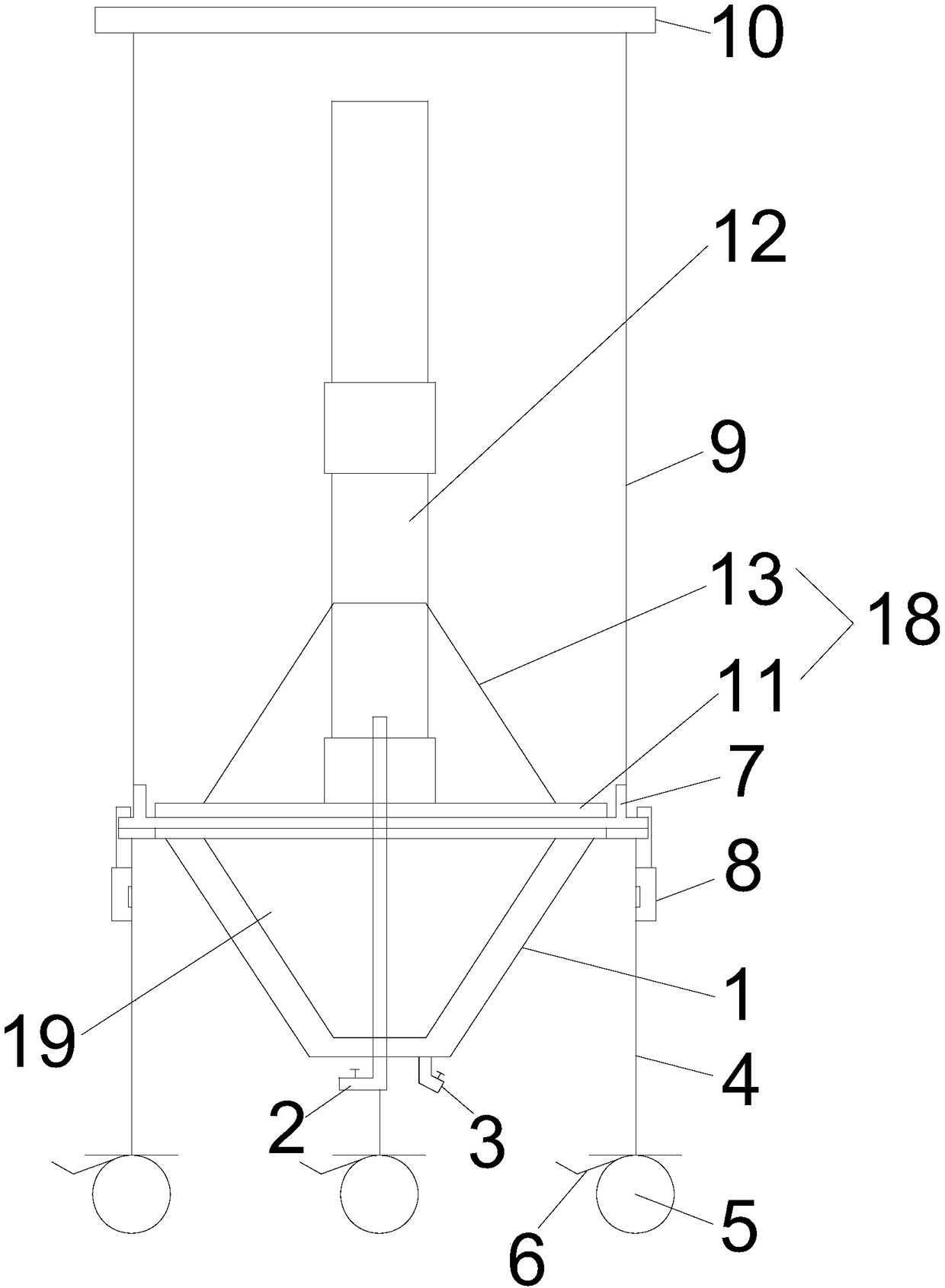
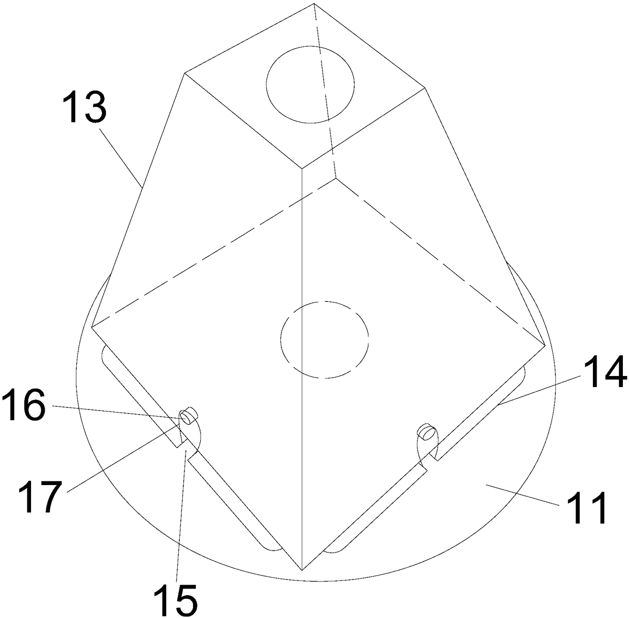
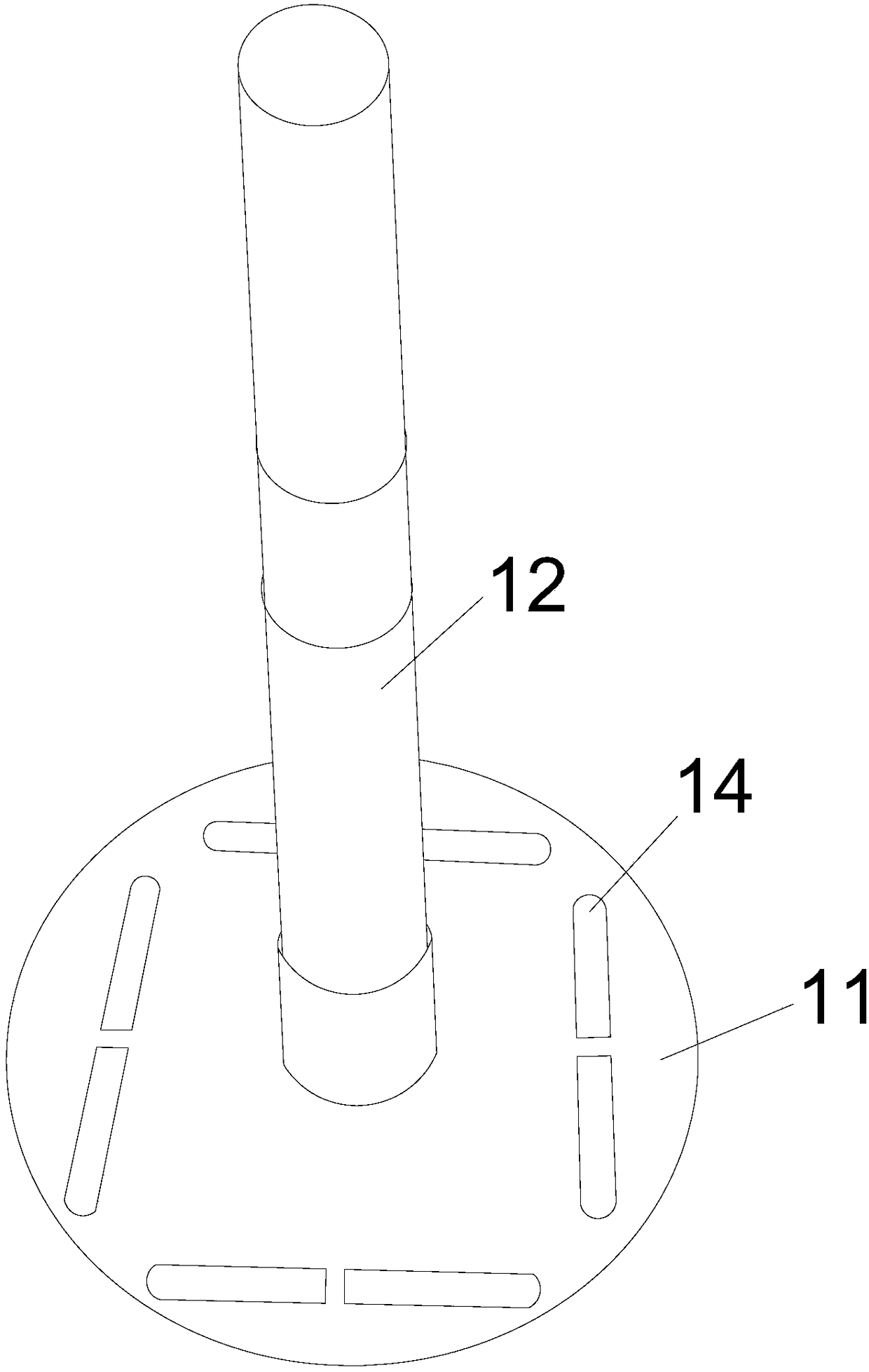
A central gaslift type efficient bioreactor is characterized in that a connecting sleeve is arranged above a container pedestal, the connecting sleeve is connected with the container pedestal througha latch assembly, a cylindrical tube wall is arranged above the connecting sleeve, an end cover is arranged above the cylindrical tube wall, a first flow guiding assembly is arranged in the cylindrical tube wall, the first flow guiding assembly comprises a first flow guiding chassis and a first flow guiding sleeve, the first flow guiding sleeve is arranged above the first flow guiding chassis, a flow guiding tube is arranged above the first flow guiding chassis, the first flow guiding sleeve is jacketed to the lower side of the flow guiding tube, the flow guiding tube is communicated with thecontainer pedestal, and the first flow guiding chassis provided with a plurality of flow guiding hole. The main body reaction part of the bioreactor adopts an acrylic material, so the bioreactor ensures enough lights, meets high-density culture demands and has a wide application range; a gaslift type cycle stirring mode is adopted to achieve a uniform mixing state, so a good growth environment isprovided for organisms in a culture solution, and the production efficiency is increased; and the container pedestal adopts an inverted quadrangular frustum, so the adhesion phenomenon is reduced.

Description

technical field [0001] The invention belongs to the technical field of bioelectronic equipment, and in particular relates to a central gas-lift high-efficiency bioreactor. Background technique [0002] Photoreactors are divided into open and closed. The operating conditions of the open photobioreactor are easier to control than the closed one, and are also greatly affected by the external environment. In addition, the investment cost of the open photobioreactor is low, and the related The equipment requirements are not as precise as the closed type, and the floor space is also small. If it is distinguished by form, it can be divided into horizontal type and inclined type (vertical type). The horizontal type photobioreactor means that the reactor system is placed horizontally on the ground. The nutrient solution in the reactor cannot be supplied by itself and must be passed through the paddle. Rotation of the wheel or rotating arm causes the culture fluid to circulate. The ...

Claims


Application Information

Patent Timeline
IPC IPC(8): C12M1/02C12M1/00C12M3/00
CPCC12M21/02C12M23/02C12M27/02
Inventor 郭敬承
Owner 郭敬承
Learn More