Solar energy biogas slurry evaporation and concentration device

An evaporation concentration, solar energy technology, applied in evaporation, cascade evaporator, evaporator accessories and other directions, can solve the problems of high operation requirements, complex system, high cost, and achieve the effect of low operation cost, improved concentration efficiency and convenient operation.

Pending Publication Date:
View PDF4 Cites 4 Cited by
  • Summary
  • Abstract
  • Description
  • Claims
  • Application Information

AI Technical Summary

Problems solved by technology

[0005] The purpose of the present invention is to provide a solar biogas slurry evaporation and concentration device with a compact structure in order to solve the defects of the existing biogas slurry concentration technology and devices in the process of biogas slurry concentration, such as large energy consumption, high cost, complex system, and high operation requirements. , No need to frequently replace components, maintenance-free, low investment cost, low energy consumption, convenient operation and easy to promote solar biogas slurry evaporation concentration device

Method used


Image

  • Solar energy biogas slurry evaporation and concentration device
  • Solar energy biogas slurry evaporation and concentration device
  • Solar energy biogas slurry evaporation and concentration device

Examples


Embodiment 1

[0027] Embodiment 1 (basic embodiment)

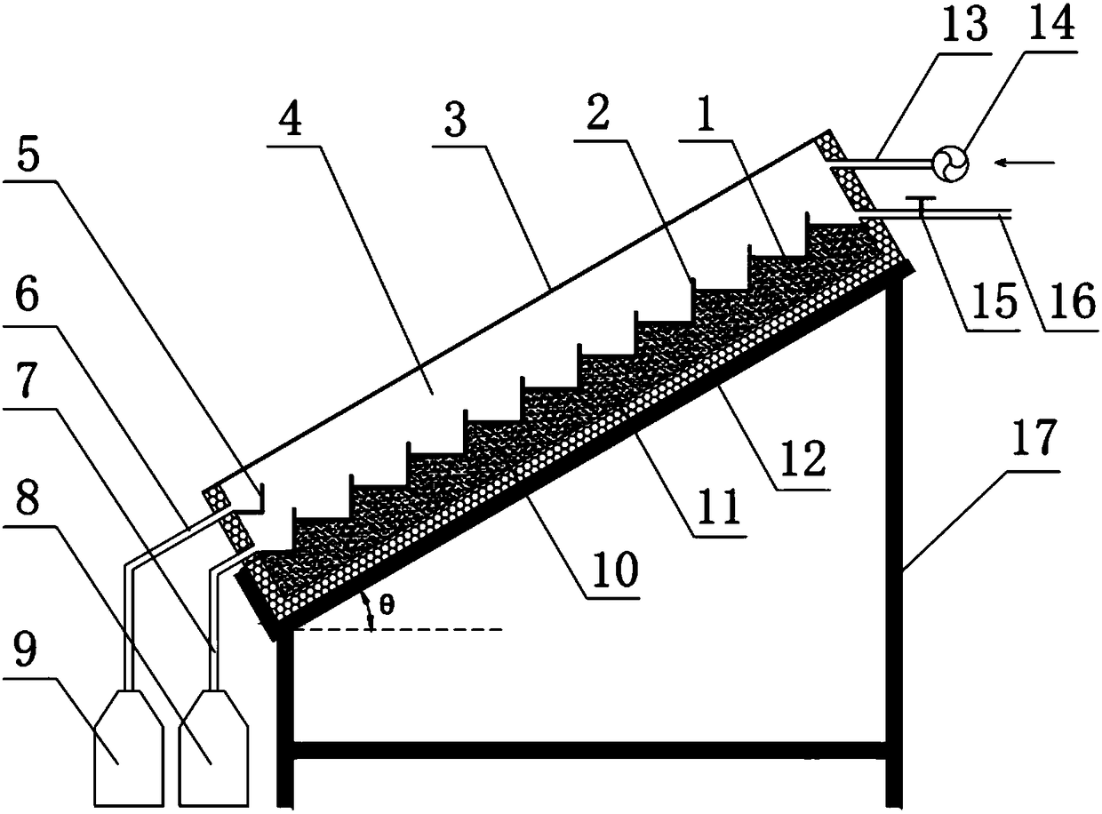
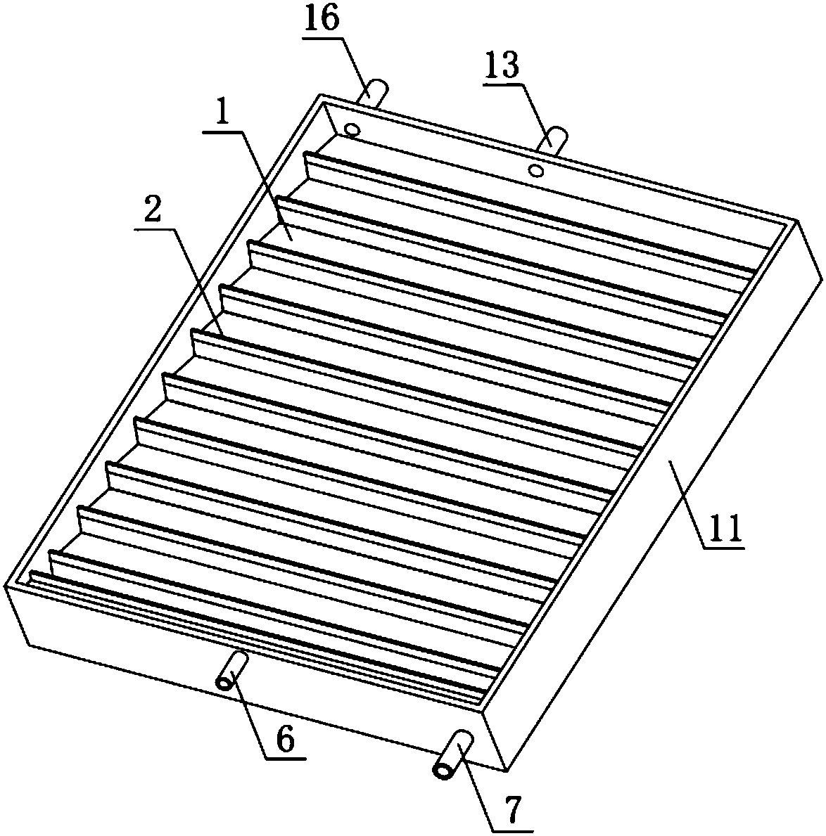
[0028] The invention is a solar biogas slurry evaporation and concentration device, the device includes: a heat collecting plate, a transparent cover plate, a distiller shell, a distillation chamber, a distillate collection tank, a heat storage material, a thermal insulation material layer, and a distillate recovery pool , Concentrate recovery tank, fan and inverted trapezoidal support. The heat collecting plates are placed inside the still shell. Water baffles are placed on the edge of each heat collector plate 1, and the length of the water baffles is equal to the length of the heat collectors so that the biogas slurry flows in a straight line (see Figure 4 ), or the length of the water baffle is less than the length of the collector plate and they are arranged in a staggered manner (see Figure 6 ), so that the biogas slurry is S-flow. The transparent cover plate is placed on the top of the distiller shell, and an airtight distill...

Embodiment 2

[0039] combine figure 1 and 3 Embodiments of the present invention will be described. This embodiment is a micro-negative pressure solar biogas slurry evaporation and concentration device. Among them, the length of the heat collecting plate can be 1m, the width of the horizontal part is 0.05m, and the width of the vertical part is 0.03m, and there are 20 steps in total. The length of the water retaining plate can be 1m, the height can be 10mm, and the total area of ​​the heat collecting plate and the water retaining plate is 1.8m 2 , The transparent cover plate is 4mm tempered glass (the sunlight transmittance is not less than 90%), and the fan is 40W exhaust fan. The thermal storage material is paraffin wax, and the thermal insulation material is rubber and plastic thermal insulation material. The installation angle (horizontal angle) between the evaporative concentration device and the horizontal plane is 30°. The evaporation and concentration device of the present inv...

Embodiment 3

[0041] combine figure 2 and 3 Embodiments of the present invention will be described. This embodiment is a micro positive pressure solar biogas slurry evaporation and concentration device. Compared with the solar biogas slurry evaporation and concentration device described in Embodiment 1, the fan is improved in the evaporation and concentration device of this embodiment. In this embodiment, the length of the heat collecting plate can be 1m, the width of the horizontal part can be 0.05m, and the width of the vertical part can be 0.03m, and there are 20 steps in total. The length of the water retaining plate can be 1m, the height can be 10mm, and the total area of ​​the heat collecting plate and the water retaining plate can be 1.8m 2 , the transparent cover is 4mm tempered glass (sunlight transmittance not less than 90%), the fan is 40W inlet fan, the heat storage material is paraffin wax, and the insulation material is rubber and plastic insulation material. The installa...


PUM

PropertyMeasurementUnit
angleaaaaaaaaaa
lengthaaaaaaaaaa
areaaaaaaaaaaa

Abstract

The invention relates to a solar energy biogas slurry evaporation and concentration device, which comprises a heat collecting plate, a transparent cover plate, a distillation device case, a distillation chamber, a distillation liquid collecting groove, a distillation liquid recovery pool, a concentration liquid recovery pool and the like, wherein the heat collection plate is arranged in the distillation device case; a water baffle plate is arranged at the edge of each layer of heat collection plate; the length of the water baffle plate is identical to the length of the heat collection plate; the biogas slurry flows in a direct flow mode; or the length of the water baffle plate is smaller than the length of the heat collection plate, and the water baffle plates are in staggered arrangement;the biogas slurry flows in an S shape; the transparent cover plate is arranged at the upper part of the distillation device case; the distillation chamber is arranged between the transparent cover plate and the heat collection plate; the upper end of the distillation chamber is connected with a feeding pipe and an air inlet/exhaust pipe; the lower end of the distillation chamber is connected withthe distillation liquid discharge pipe and the concentration liquid discharge pipe; the air inlet/exhaust pipe is connected with a fan; the distillation liquid collection groove is fixedly arranged in the distillation case; the distillation liquid discharge pipe and the distillation liquid recovery pool are connected; the concentration liquid recovery pool is connected with the heat collection plate; paraffin is arranged in the lower part of the heat collection plate; a heat insulation material is arranged at the periphery and the bottom of the distillation device case; the integral device ispositioned on a reverse trapezoidal support frame.

Description

technical field [0001] The invention belongs to the technical field of rural renewable energy utilization and is related to the field of concentration and utilization of biogas slurry. In particular, the invention relates to a solar energy biogas slurry evaporation and concentration device. Background technique [0002] The output of agricultural waste in China's rural areas is increasing year by year, and the characteristics of biogas projects in agricultural waste reduction, recycling, and harmlessness have attracted more and more people's attention and developed rapidly. However, biogas projects will produce a large amount of biogas slurry while producing biogas. Due to the large amount of biogas slurry produced and the low nutrient concentration, it has caused great difficulties in its treatment and utilization, and has become a bottleneck restricting the development of the biogas industry. Therefore, the concentration and reduction of biogas slurry is a way of resource ...

Claims


Application Information

Patent Timeline
Patent Type & Authority Applications(China)
IPC IPC(8): C02F1/14B01D1/00B01D1/30B01D3/00
CPCB01D1/0035B01D1/0088B01D1/30B01D3/00C02F1/043C02F1/14Y02A20/212
Inventor 袁巧霞王攀攀
Why Eureka
Try Eureka