
Power generating system utilizing vaporization latent heat of exhaust fume of natural gas power plant

A technology of power generation system and latent heat of vaporization, which is applied in liquefaction, steam engine installation, refrigeration and liquefaction, etc. It can solve the problems of low power generation efficiency of the system, high energy consumption of carbon capture link, waste of latent heat of main flue gas, etc., and achieve easy heat exchange Process, small size, and the effect of improving power generation efficiency

Active Publication Date: 2018-07-27
HUAZHONG UNIV OF SCI & TECH
View PDF3 Cites 15 Cited by
  • Summary
  • Abstract
  • Description
  • Claims
  • Application Information

AI Technical Summary

Problems solved by technology

Correspondingly, the present invention optimizes the heat exchange effect, recycles and utilizes the latent heat of vaporization in the flue gas, and significantly improves the power generation efficiency of the combined cycle; at the same time, it realizes zero emission of carbon and has a good environmental protection effect, thus solving the problem of the existing power generation technology in power plants. Serious waste of main flue gas latent heat, low power generation efficiency of the system, high energy consumption in carbon capture, and serious waste of LNG cold energy

Method used


Image

  • Power generating system utilizing vaporization latent heat of exhaust fume of natural gas power plant

Examples


Embodiment Construction

[0034] In order to make the object, technical solution and advantages of the present invention clearer, the present invention will be further described in detail below in conjunction with the accompanying drawings and embodiments. It should be understood that the specific embodiments described here are only used to explain the present invention, not to limit the present invention. In addition, the technical features involved in the various embodiments of the present invention described below can be combined with each other as long as they do not constitute a conflict with each other.

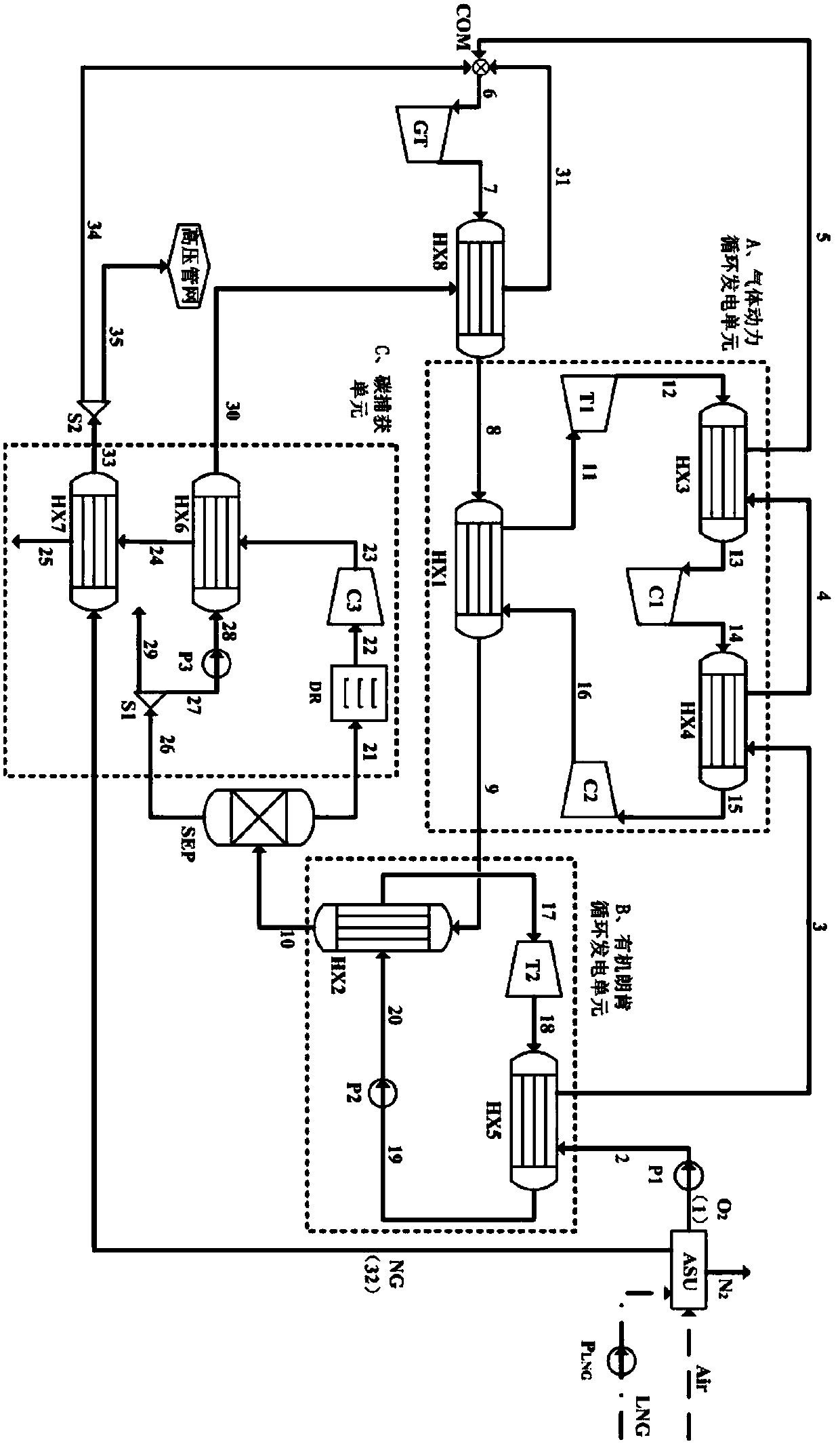
[0035] The present invention provides a power generation system utilizing the latent heat of vaporization of exhaust gas from a natural gas power plant. The system is aimed at an oxygen-enriched combustion natural gas power plant and proposes a compound combined cycle power generation unit, including an oxygen-enriched burner COM, a gas turbine GT, Circulation power generation unit A, organic Ra...


PUM


Abstract

The invention discloses a power generating system utilizing vaporization latent heat of exhaust fume of a natural gas power plant. According to the power generating system, aiming at the oxygen enriched combustion natural gas power plant, a composite-type combined cycling power generating unit is put forward, fume generated after oxygen enriched combustion sequentially passes through a combustiongas turbine GT, a gas power cycling power generating unit A and an organic Rankine cycle power generating unit B, the vaporization latent heat in the fume can be sufficiently recycled, the temperatureof the exhaust fume is decreased to below the normal temperature, CO2 and water in the fume are separated accordingly, and carbon capture is achieved. In the power generating system, gas power cycling is adopted, thus phase change of heat exchange media is avoided, and the heat exchange effect is improved; through organic Rankine cycle, the vaporization latent heat in the fume is sufficiently recovered, and the power generating efficiency of the system is greatly improved; and according to the integrated power generating system, the problems that the steam vaporization latent heat in the low-temperature fume is generally wasted, carbon capture energy consumption is high, and LNG cold energy waste is serious can be effectively solved, meanwhile the power generating efficiency of the systemis improved, and energy saving, environmental friendliness and high efficiency are achieved truly.

Description

technical field [0001] The invention belongs to energy technology and power industry to realize CO 2 The field of zero-emission high-efficiency power generation system, more specifically, relates to a power generation system that utilizes the latent heat of vaporization of exhaust smoke from a natural gas power plant. Background technique [0002] LNG is a liquefied natural gas with a temperature of about -162°C under normal pressure. The gasification process will release about 830kJ / kg of cold energy, which has great utilization value. However, from a global perspective, the utilization rate of LNG cold energy is only about 20%, and the utilization rate of cold energy resources is low. Serious waste. In addition, the greenhouse effect has intensified, and my country is facing severe pressure to reduce emissions. Studies have shown that CO in the atmosphere 2 It is one of the gases that have the greatest impact on the greenhouse effect. Carbon capture and storage (CCS)...

Claims


Application Information

Patent Timeline
IPC IPC(8): F01K13/00F01K23/02F01D15/10F02C6/18F25J3/06
CPCF01D15/10F01K13/00F01K23/02F02C6/18F25J3/067F25J2215/80F25J2210/70F25J3/04266F25J3/04533F25J2260/02F25J2260/80F25J2240/82F25J2235/50F25J2250/50Y02C20/40
Inventor 蔡磊梁莹管延文刘文斌向艳蕾韩逸骁高奕刘海天吴逸倩刘泽曦余露杨云李伟杰
Owner HUAZHONG UNIV OF SCI & TECH
Learn More