
Biological aerosol real-time detection method and device based on laser induced fluorescence

A laser-induced fluorescence and bio-aerosol technology, applied in the field of air microorganism and particulate matter monitoring, can solve the problems of space separation and culture automation, difficulty in realizing space separation and culture, difficulty in dispersing the sample to be tested into single cells, and inability to cultivate and detect bacteria, and achieve real-time performance. Strong, easy-to-operate, high-sensitivity effects

Pending Publication Date: 2018-08-07
NANJING UNIV OF TECH
View PDF9 Cites 10 Cited by
  • Summary
  • Abstract
  • Description
  • Claims
  • Application Information

AI Technical Summary

Problems solved by technology

[0006] There is following shortcoming in above-mentioned existing method: (1) because the sample to be tested is not easy to disperse into single cell completely, so the bacterium colony that forms is not all single bacterium colony, has a part to grow into by more than two cells, so plate colony count The test result will be lower than the actual number of colonies
(2) Some bacteria cannot be cultured and detected, or the culture medium can only select and cultivate some strains, thus limiting the scope of application of this method
(3) The detection period of this method is long, and the automatic operation of space separation culture is difficult to realize

Method used


Image

  • Biological aerosol real-time detection method and device based on laser induced fluorescence
  • Biological aerosol real-time detection method and device based on laser induced fluorescence
  • Biological aerosol real-time detection method and device based on laser induced fluorescence

Examples


Embodiment Construction

[0028] The present invention will be further described through the embodiments below in conjunction with the accompanying drawings, so as to better understand the present invention.

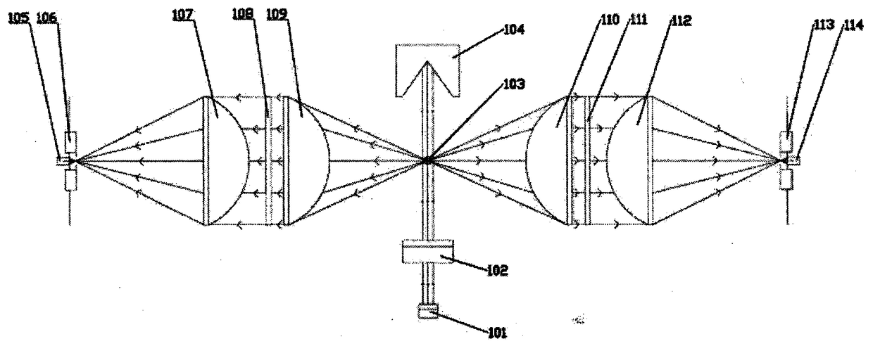
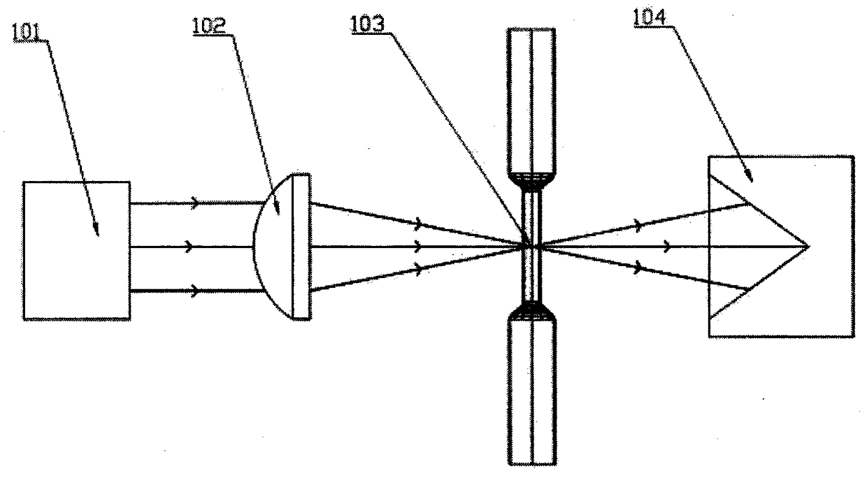
[0029] Such as figure 1 As shown, the laser emitting optical path includes a semiconductor laser 101 , a plano-convex cylindrical mirror 102 , and an optical trap 104 . The laser light emitted by the semiconductor laser is one-dimensionally focused into an elongated light spot by the plano-convex cylindrical mirror 102 . The focal line of the cylindrical lens 102 intersects with the central axis of the gas pipeline to form a photosensitive area, and the intersection point is the center 103 of the photosensitive area.

[0030] The scattered light collection optical path includes a plano-convex lens 109 perpendicular to the laser irradiation direction to the left, a long-wave cut filter 108 , a plano-convex lens 107 , a scattered light diaphragm 106 , and a scattered light detector 105 . The mixe...


PUM


Abstract

The invention discloses a biological aerosol real-time detection method and device based on laser induced fluorescence. The primary parts of the device comprise a light path, a gas circuit intersectedwith the light path, and a signal processing system connected to the light path. The light path comprises a laser emitting light path, a scattered light receiving light path and a fluorescence receiving light path; the gas circuit is used for sampling to-be-detected particles; the signal processing system is used for analyzing and processing signals and comprises a scattered light processing system and a fluorescence processing system. Based on the principle of laser induced fluorescence, grain sizes and concentration of microbial particles and non-biological particles in air can be monitoredin real time. The grain size and the biological attribute of the to-be-detected particle are judged through the scattered light and fluorescence signals generated by the single particle under irradiation of laser, and the particles in a sampled air flow are counted, so that the concentration of microorganisms in air is detected automatically. The biological aerosol real-time detection method anddevice are simple to operate, high in real-time monitoring, high in sensitivity and high in accuracy.

Description

technical field [0001] The invention belongs to the field of air microorganism and particle monitoring, and in particular relates to a bioaerosol real-time monitoring method and device thereof, which can monitor the concentration, quantity, particle size, etc. of microbial particles such as bacteria and fungi in the air. Background technique [0002] The microorganisms that can survive in the air mainly include: (1) bacteria and viruses. The main indoor bacteria and viruses are hemolytic streptococcus, viridans streptococcus, pneumococcus, influenza virus, meningococcus, Mycobacterium tuberculosis, measles virus and so on. These bacteria and viruses can be spread by attaching to dust in the air. Through activities such as talking, coughing, and sneezing, people can spray pathogenic microorganisms in the mouth, throat, trachea, and lungs into the air through droplets and spread them to others. There may be more pathogenic microorganisms in indoor air, especially in poorly v...

Claims


Application Information

Patent Timeline
IPC IPC(8): G01N15/02G01N15/06G01N21/64
CPCG01N15/0211G01N15/06G01N21/6402G01N15/075
Inventor 张玉贵周斌孙子健成政梅建军牛潜
Owner NANJING UNIV OF TECH
Learn More