

Forming method of composite material winding shaft containing injection layer
A technology of composite materials and molding methods, which is applied in the field of mold molding, can solve problems such as winding shafts that cannot be molded, and achieve the effects of reducing time consumption, improving efficiency, and simplifying the manufacturing process
- Summary
- Abstract
- Description
- Claims
- Application Information
AI Technical Summary
Problems solved by technology
Method used
Image

Examples
specific Embodiment approach 1
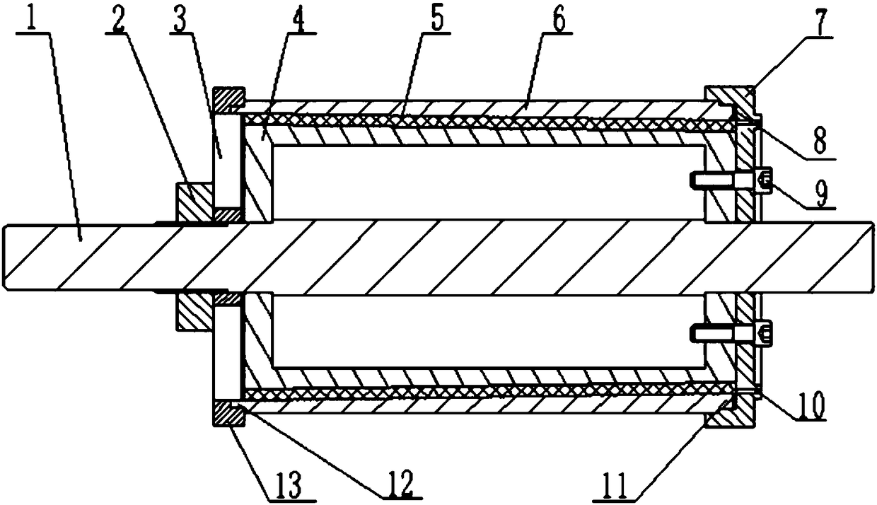
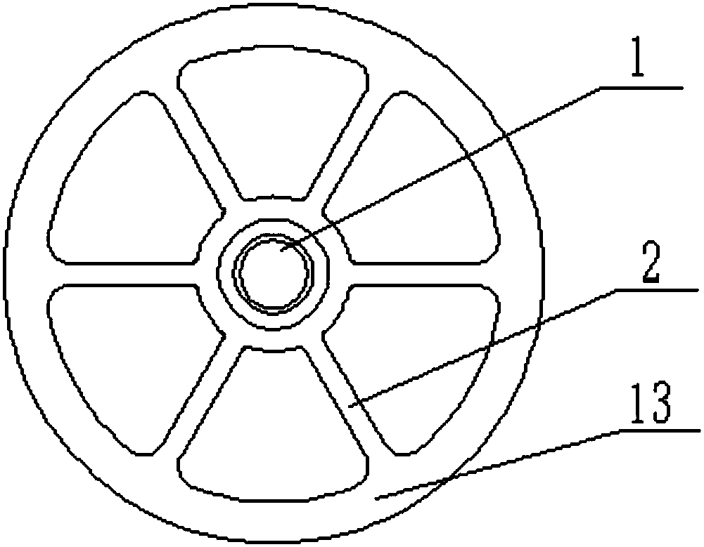
[0026] Specific implementation mode one, combining figure 1 , 2 This embodiment will be described. The bobbin forming method described in this embodiment realizes the bobbin forming by using a bobbin forming die, wherein the bobbin forming die includes a central shaft 1 , a left clamping ring 2 , a left support ring 3 , and a mold body 4 , flow interlayer 5, outer mold 6, sealing end cap 7, washer 8, fastening screw 9, carbon fiber and injection hole 10, the method for described bobbin molding comprises the following steps:
[0027] Step 1, the mold body 4 is installed on a horizontal winding machine, after polishing the outer surface of the mold body 4 with 200 mesh sandpaper, the surface of the mold body 4 is cleaned and polished with cotton yarn, and brushed on the mold body 4 apply release agent;
[0028] Step 2, apply body glue on the surface of the mold body 4 coated with the mold release agent in step 1, install the carbon fiber on the winding tensioner of the horizo...
specific Embodiment approach 2
[0041] Specific implementation mode two, see figure 1 This embodiment will be described. This embodiment is a further limitation of the method for forming a composite bobbin with an injection layer described in the first embodiment. The body glue described in step two in this embodiment is made of resin and curing agent in a weight ratio of 1 A colloid prepared at a ratio of :1.
[0042] The combination of the colloid components and their weight ratios in this embodiment is beneficial to solve the problem of mismatching coefficients of thermal expansion of various materials.
specific Embodiment approach 3
[0043] Specific implementation mode three, see figure 1 This embodiment will be described. This embodiment is a further limitation of the method for forming a composite material bobbin with an injection layer described in the first embodiment. The total thickness of the dipping material is 0.15-1 mm.
[0044] The thickness of the carbon fiber prepreg described in this embodiment is conducive to enhancing the rigidity of the first hoop-wound carbon fiber layer of the composite material.
PUM
| Property | Measurement | Unit |
|---|---|---|
| Angle | aaaaa | aaaaa |
| Thickness | aaaaa | aaaaa |
| Thickness | aaaaa | aaaaa |
Abstract
Description
Claims
Application Information