Deep ultraviolet narrow band filter

A narrow-band filter and filter technology, applied in the direction of optical filters, optics, optical components, etc., can solve the problems of low short-wave transmittance, low peak transmittance, and difficult filter cut-off, so as to reduce reflected light , reduce the bandwidth, improve the effect of transmittance

Pending Publication Date: 2018-08-10
德州尧鼎光电科技有限公司
View PDF6 Cites 4 Cited by
  • Summary
  • Abstract
  • Description
  • Claims
  • Application Information

AI Technical Summary

Problems solved by technology

In most applications, the bypass band must be suppressed: usually the short-wave bypass band can be removed by superimposing a long-wave pass absorption glass filter on the filter, although the short-wave pass absorption glass filter can effectively suppress the long-wave pass band. Sideband, but its short-wave transmittance is too low, which reduces the peak transmittance of the overall film system, and it is very difficult to cut off the filter in the range of 200nm-250nm, because there is no short-wave pass absorption in this spectral range glass filter
There are two cut-off methods in the current research, one is to increase the metal-dielectric filter, and the other is to connect the mirror in series with the filter to obtain the cut-off. The advantage is that there is no long-wave bypass passband. The disadvantage is that the peak transmittance is very low and the half width is very large, so that the cutoff and passband shape cannot be used.

Method used


Image

  • Deep ultraviolet narrow band filter
  • Deep ultraviolet narrow band filter
  • Deep ultraviolet narrow band filter

Examples


Embodiment 1

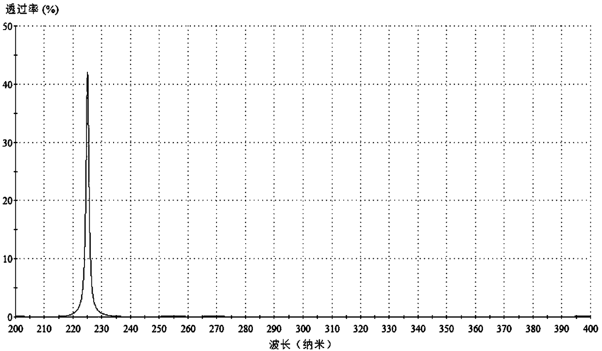
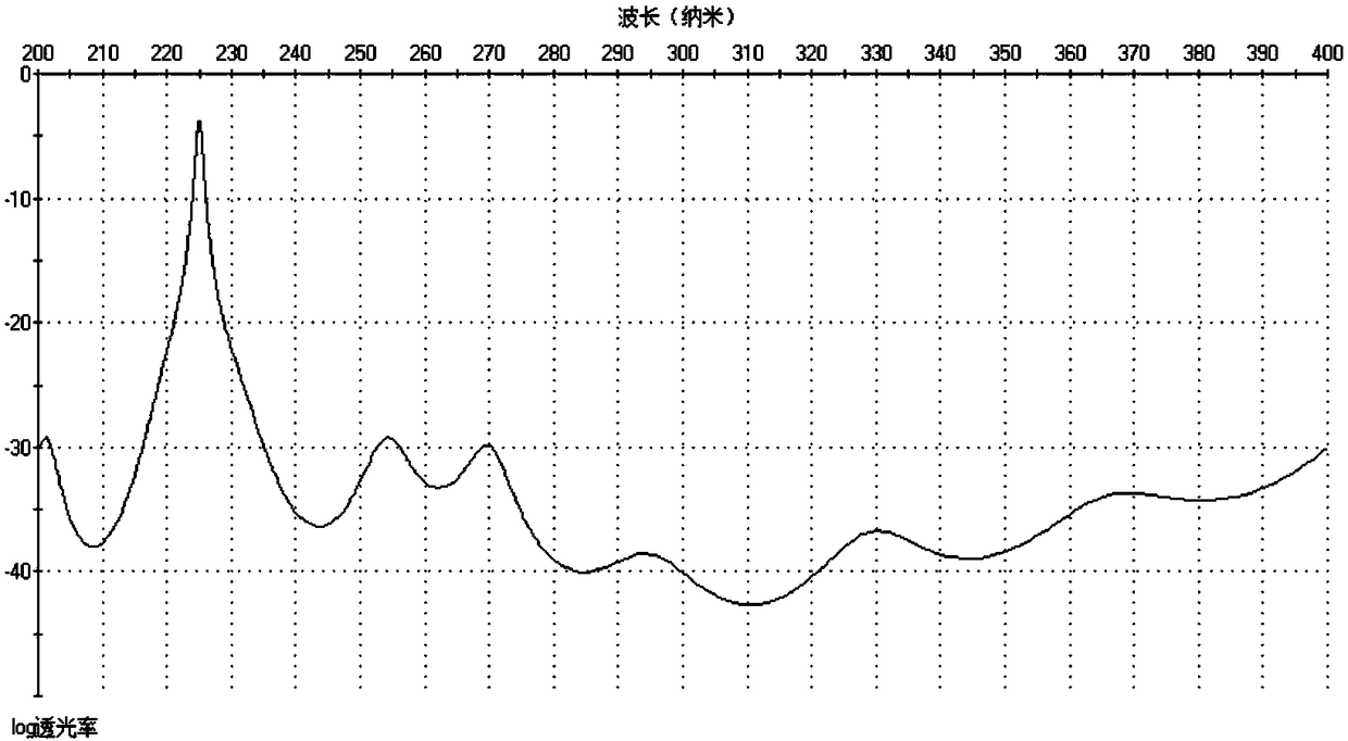
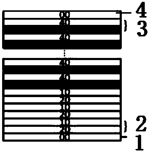
[0068] The main structure of the deep ultraviolet narrow-band filter involved in this embodiment includes a base layer 1, a filter layer 2, a film layer 3 and a protective layer 4; the upper surface of the base layer 1 is deposited with 3 layers of filter layers 2, and finally The upper surface of the upper filter layer 2 is deposited with 13 film layers 3; the base layer 1 is JGS1; the main structure of the filter layer 2 includes the filter layer spacer layer 10 and the reflective layer 20, and the upper surface of the reflective layer Deposit the filter layer spacer layer 10, the filter layer spacer layer 10 is SiO 2 , the reflective layer 20 is Al, and the filter layer 2 is a double half-wave F-P interference filter structure (Al / SiO 2 / Al / SiO 2 / Al / SiO 2 ), metal Al has a large extinction coefficient and high reflection characteristics in the visible light band, Al and SiO 2 The combination can realize the depth cut-off of specific waveband and the high transmittance i...

Embodiment 2

[0072] The preparation process of the deep ultraviolet narrow-band filter involved in this embodiment includes five steps: designing the film system formula, preparing the base layer, preparing the filter layer, preparing the film layer and controlling the thickness of the film layer:

[0073] (1) Design film system formula: JGS1, Al, SiO selected according to Example 1 2 、 Al 2 o 3 and MgF 2 The technical requirements of the refractive index, extinction coefficient and bandwidth of less than 2nm are designed to design a film system formula: SiO 2 |HMH H2MH(MH)^2M(HM)^2H2MH(MH)^2 (NL)^3|JGS1, where L is Al and H is Al 2 o 3 , M is MgF 2 , N is SiO 2 , use Essential Macleod (optical thin film analysis and design software) or TFCalc (thin film design software) to simulate, optimize and change the physical thickness value of the film system formula;

[0074] (2) Preparation of base layer: cutting JGS1 into base layer 1 according to the set size;

[0075] (3) Prepare the f...


PUM


Abstract

The invention belongs to the technical field of thin film optics, and relates to a deep ultraviolet narrow band filter. The main structure of the deep ultraviolet narrow band filter comprises a base layer, a filter layer, a film layer and a protective layer. According to the deep ultraviolet narrow band filter, a design concept of the F-P band-pass filter film is used for designing a metal-mediumcombined transmission filter, a tandem metal-medium filter is selected to suppress a sideband of a long-wavelength region, an all-media filter is used for reducing the bandwidth, a multilayer film structure composed of a high refractive index material/ low refractive index material is in tandem arrangement on the basis of a double half-wave F-P interference filter structure to form an F-P filter with a simple structure, the depth cutoff in a specific deep ultraviolet wave band is achieved in a wavelength band, by changing the shape of the filter layer, the half-bandwidth of the deep ultraviolet narrow band filter is reduced to separate a selected film layer from a film system, the combination of the entire film system is represented by two selected effective interfaces, as long as the multi-beam interference of the selected film layer is considered, the optical properties of the multilayer film are solved, and the method for designing the film system is obtained.

Description

Technical field: [0001] The invention belongs to the technical field of thin-film optics and relates to a deep ultraviolet narrow-band filter. The prepared filter has narrow bandwidth and high transmittance, can realize a wide range of depth cut-off, and solves the problem of deep ultraviolet filtering. Background technique: [0002] The filter is an optical device used to select the required radiation band. The commonality of the filter is that no filter can make the image of the celestial body brighter, because all filters will absorb certain wavelengths, so that the Objects become darker. The filter is made of plastic or glass with special dyes added. The red filter can only let red light pass through, and so on. The transmittance of the glass sheet is almost the same as that of air, and all colored light can pass through, so it is transparent. Yes, but after dyeing the dye, the molecular structure changes, the refractive index also changes, and the passage of certain co...

Claims


Application Information

Patent Timeline
Patent Type & Authority Applications(China)
IPC IPC(8): G02B5/20G02B5/26
CPCG02B5/208G02B5/201G02B5/26
Inventor 吴锜佟瑶窦琳
Owner 德州尧鼎光电科技有限公司
Why Eureka
Try Eureka