Steel-structure automatic-impact positioning and monitoring test platform based on optical fiber grating

A fiber grating and test platform technology, applied in the direction of measuring devices, optical devices, instruments, etc., can solve the problems of electromagnetic interference, inconvenient operation, and deviation, so as to avoid complexity and inaccuracy, high reliability and Accuracy, the effect of avoiding secondary impact

Pending Publication Date: 2018-08-17
CHINA UNIV OF PETROLEUM (EAST CHINA)
View PDF8 Cites 7 Cited by
  • Summary
  • Abstract
  • Description
  • Claims
  • Application Information

AI Technical Summary

Problems solved by technology

[0004] (1) Traditional impact location monitoring systems are usually based on resistance strain gauge sensors. Although resistance strain gauges are widely used in large-scale engineering structures, they have a short lifespan, are easily affected by the environment, and are seriously affected by electromagnetic interference. Disadvantages, and once the number of measuring points increases, its maintenance and testing costs will increase greatly
Considering the environment of the ship, electromagnetic interference, humidity, chemical corrosion are serious, as well as hull vibration, wave slamming, etc., which interfere a lot with the signal, so the resistance strain sensor is not suitable for long-term, real-time online distribution of the hull steel structure. monitor;
[0005] (2) The traditional impact device is usually placed on the surface of the steel structure to be tested, and the instrument itself will have a certain impact on the steel structure, thereby reducing the accuracy of the actual monitoring results;
[0006] (3) When the traditional impact device determines the release position of the steel ball, it is usually manually adjusted according to the scale value of the XYZ three-axis direction, which is inconvenient to operate and often deviates from the ideal position;
[0007] (4) After the steel ball completes the free fall motion, the traditional impact device usually uses manual methods to quickly remove the steel ball to avoid the secondary impact of the steel ball, but this method has great limitations and inoperability

Method used


Image

  • Steel-structure automatic-impact positioning and monitoring test platform based on optical fiber grating
  • Steel-structure automatic-impact positioning and monitoring test platform based on optical fiber grating
  • Steel-structure automatic-impact positioning and monitoring test platform based on optical fiber grating

Examples


Embodiment Construction

[0040] The present invention will be further described below in conjunction with the accompanying drawings and embodiments.

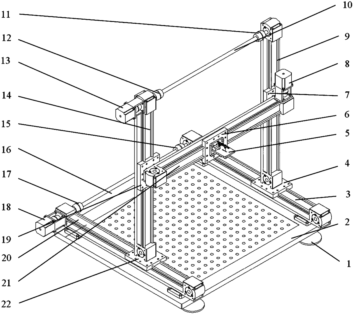
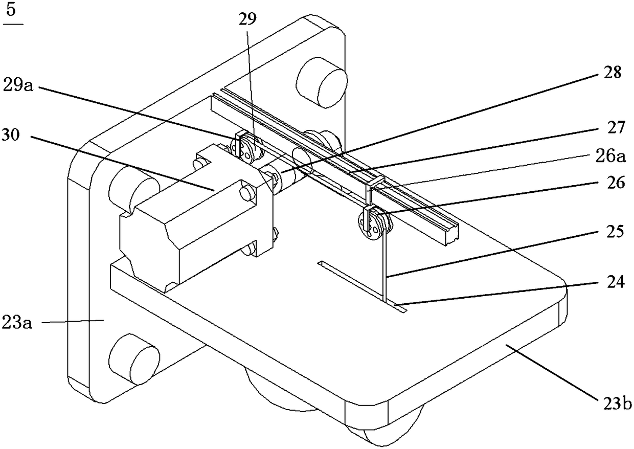
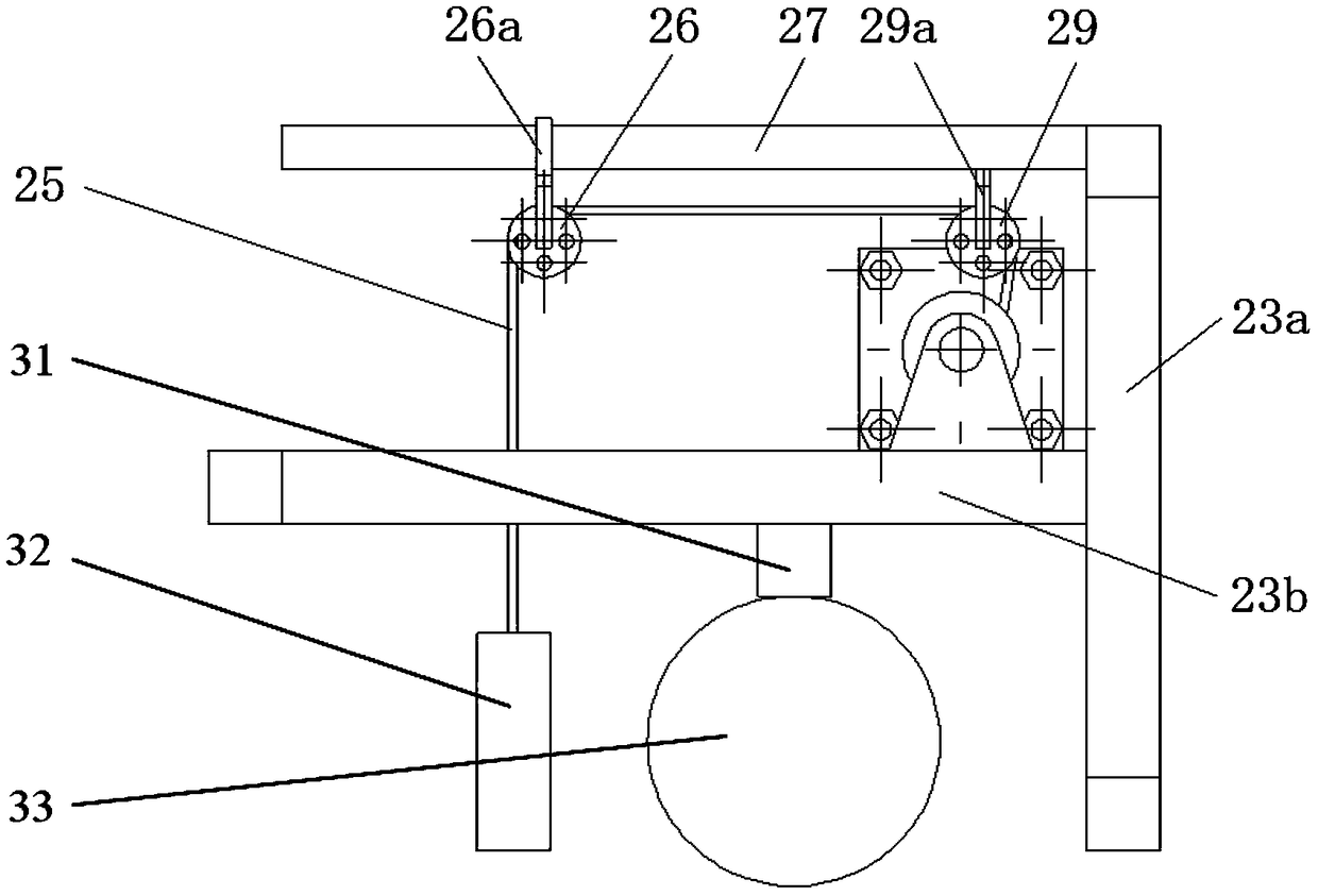
[0041] figure 1 It is a structural schematic diagram of the fiber grating-based steel structure automatic impact positioning monitoring test platform of the present invention; figure 2 It is a perspective view of the steel ball control device of the present invention; image 3 yes figure 2 The right view of the middle steel ball control device; Figure 4 It is a schematic diagram of the impact location monitoring system of the present invention.

[0042] Such as figure 1As shown, the steel structure automatic impact positioning monitoring test platform based on optical fiber gratings includes a test piece fixing table 2, a steel ball control device 5 and a control system and an impact positioning monitoring system; the test piece fixing table 2 is fixed with a test piece; A steel ball 33 is placed in the steel ball control device 5;

[0043] An ...


PUM


Abstract

The invention discloses a steel-structure automatic-impact positioning and monitoring test platform based on an optical fiber grating. The steel-structure automatic-impact positioning and monitoring test platform based on an optical fiber grating comprises a test piece fixing platform, a steel ball control device and a control system as well as an impact positioning and monitoring system, whereina test piece is fixedly arranged on the test piece fixing platform; a steel ball is placed in the steel ball control device; an X-axis slide rail, a Y-axis slide rail and a Z-axis slide rail are separately arranged on the test piece fixing platform; the Z-axis slide rail slides in the X-axis slide rail through an X-axis slide block; the Y-axis slide rail slides in the Z-axis slide rail through a Z-axis slide block; the steel ball control device is fixedly arranged on the Y-axis slide rail through a Y-axis slide block in a sliding mode; and the control system controls displacement movement, along the X-axis slide rail, the Y-axis slide rail and the Z-axis slide rail, of the steel ball control device, and controls impact action of the steel ball. The steel-structure automatic-impact positioning and monitoring test platform performs real-time online monitoring and positioning for impact damages of the steel structure, can effectively complete impact positioning and monitoring for any point in the steel structure, and has higher reliability and precision.

Description

technical field [0001] The invention relates to the technical field of a steel structure monitoring test platform, in particular to an optical fiber grating-based steel structure automatic shock positioning monitoring test platform. Background technique [0002] Steel structures are widely used in industry, for example as load-bearing components of ships. At present, due to the long-term navigation of ships in the harsh marine environment, the steel structure of the hull is extremely prone to damage caused by grounding or collision impact, which reduces the bearing capacity and performance of the steel structure and seriously affects the stability of the steel structure. In order to monitor the working conditions of the steel structure of the hull in real time and to monitor the impact that may cause major dangers, the health monitoring technology of steel structures has received more and more research and attention in the field of ships. [0003] The traditional steel stru...

Claims


Application Information

Patent Timeline
Patent Type & Authority Applications(China)
IPC IPC(8): G01N3/303G01N3/02G01B11/00
CPCG01B11/00G01N3/02G01N3/303
Inventor 肖文生刘琦刘思缈张林川李康
Owner CHINA UNIV OF PETROLEUM (EAST CHINA)
Why Eureka
Try Eureka