Laser radar optical system and laser radar

A laser radar and optical system technology, applied in the field of laser measurement, can solve the problems of the overall size of the coaxial system, the small-diameter lens that cannot be used in the receiving system, and the large volume of the coaxial system

Pending Publication Date: 2018-08-17
天津杰泰高科传感技术有限公司
View PDF5 Cites 13 Cited by
  • Summary
  • Abstract
  • Description
  • Claims
  • Application Information

AI Technical Summary

Problems solved by technology

[0004] However, the total length of the coaxial system is relatively large, and because the center of the receiving system is blocked by the transmitting system, the receiving system cannot use a small-diameter lens, resulting in a large volume of the coaxial system
For the non-coaxial system, due to the field angle of the receiving system, within a short range from the non-coaxial system, the returned light of the measured object is converged by the receiving system and deviates from the APD, so there is a measurement blind spot in the non-coaxial system

Method used


Image

  • Laser radar optical system and laser radar
  • Laser radar optical system and laser radar
  • Laser radar optical system and laser radar

Examples


Embodiment 1

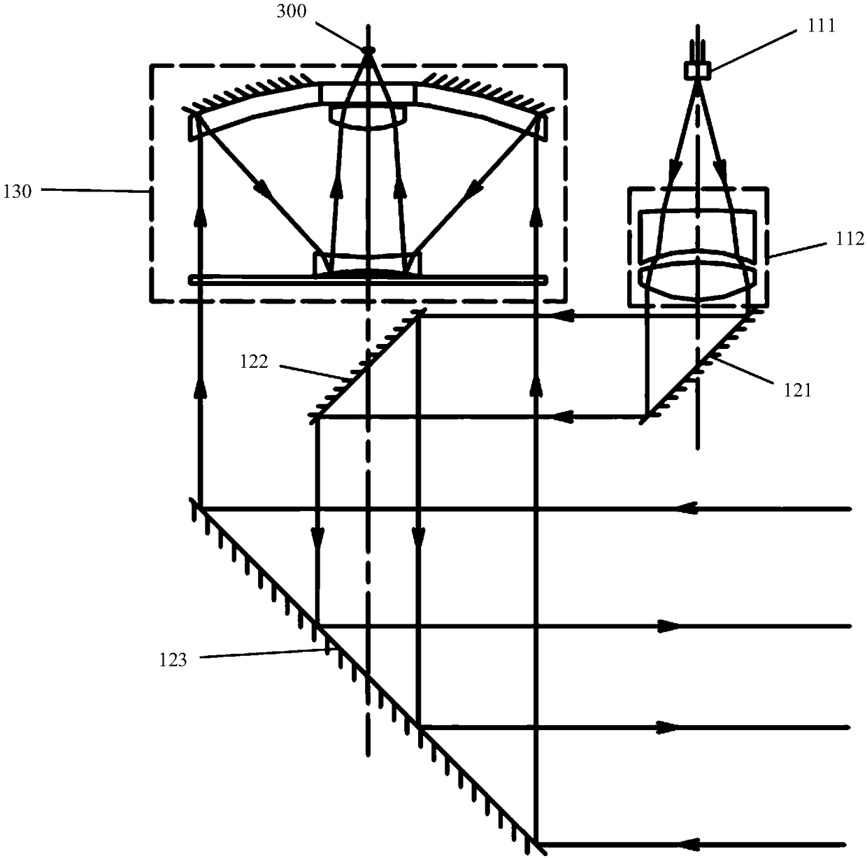
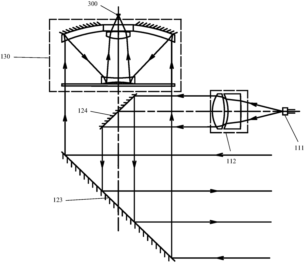
[0039] An embodiment of the present invention provides a laser radar optical system, and the laser radar optical system includes a transmitting system, a reflecting system and a receiving system. The transmitting system includes a coaxial laser light source and a collimating lens group; the reflecting system reflects the optical axis of the transmitting system to be coaxial with the optical axis of the receiving system. The laser beam emitted by the laser light source is collimated by the collimating lens group and then becomes a parallel beam and enters the reflection system; the reflection system reflects the parallel beam to the direction of the laser radar azimuth axis for scanning, and returns the reflection of the measured object in the direction of the azimuth axis The returning light is reflected to the receiving system; the receiving system gathers the reflected returning light to the light detector of the lidar.

[0040]Specifically, the laser light source can be, bu...

Embodiment 2

[0057] Figure 4 A schematic structural diagram of a laser radar provided by an embodiment of the present invention, such as Figure 4 As shown, the laser radar includes the laser radar optical system 100 as in the first embodiment above, and also includes a motor 200 , a light detector 300 and an information processing system 400 .

[0058] The motor 200 is connected with the scanning mirror 123 in the reflection system of the laser radar optical system 100, and is used to drive the scanning mirror 123 to scan; 400 connections. Such as Figure 4 As shown, the photodetector 300 is used to receive the reflected light collected by the lidar optical system 100, and send the returned light signal to the information processing system 400; the information processing system 400 receives the returned light signal, and outputs the corresponding The distance between the measured object and the lidar.

[0059] Specifically, in some possible embodiments, the light detector 300 include...


PUM


Abstract

The invention provides a laser radar optical system and laser radar and relates to the technical field of laser measurement. The laser radar optical system comprises a transmitting system, a reflecting system and a receiving system; the transmitting system includes a laser source and a collimating lens unit which are coaxially arranged; the reflecting system reflects an optical axis of the transmitting system to be coaxial with that of the receiving system; a laser beam emitted by the laser source is collimated by the collimating lens unit into a parallel beam entering the reflecting system; the reflecting system reflects the parallel beam to the azimuthal axis of the laser radar for the purpose of scanning, and reflecting reflected light, returned by an object under measurement in the azimuthal axis, to the receiving system; the receiving system gathers the reflected light to a photodetector of the laser radar. Therefore, aperture covering due to the transmitting system at the receiving system center is decreased system total length and size are decreased, and measurement blind zones due to the use of traditional noncoaxial systems are avoided.

Description

technical field [0001] The invention relates to the technical field of laser measurement, in particular to a laser radar optical system and a laser radar. Background technique [0002] With the rapid development of industry, the demand for machine intelligence in modern industry is increasing, and various automation products are developing in the direction of convenience, safety, high efficiency, high precision and miniaturization. As a reliable photoelectric sensor, LiDAR products are widely used in many fields such as obscuration, measurement, aerospace and so on. [0003] The lidar includes a transmitting system and a receiving system, and the receiving system usually includes an APD (Avalanche Photo Diode, avalanche photodiode) for detecting the scattered light (reflected light) of the measured object. The working principle of the laser radar is as follows: the laser beam is transmitted to the measured object through the transmitting system, the scattered back light of ...

Claims


Application Information

Patent Timeline
Patent Type & Authority Applications(China)
IPC IPC(8): G01S7/481
CPCG01S7/4812G01S7/4817
Inventor 张洪奇季慧卫滨
Owner 天津杰泰高科传感技术有限公司
Why Eureka
Try Eureka