Illumination system of ghost elimination eye fundus camera

A lighting system and camera technology, applied in fundus mirrors, eye testing equipment, medical science, etc., can solve the problems of uncompact structure, easy ghosting, low light efficiency, etc., and achieve simple structure and good ghosting effect. , uniform lighting effect

Pending Publication Date: 2018-08-24
UNION OPTECH
View PDF1 Cites 3 Cited by
  • Summary
  • Abstract
  • Description
  • Claims
  • Application Information

AI Technical Summary

Problems solved by technology

[0002] Since the fundus itself does not emit light, and the diameter of the pupil generally does not exceed 3mm during the day, it is required that the light from the lighting equipment and the light from the imaging equipment pass through such a small aperture at the same time to achieve uniform illumination and imaging without ghosting. Traditional ring lighting requires The illumination source is a ring or an array surface light source plus a ring diaphragm or directly adopts the optical fiber external lighting and the imaging system does not share the lens. If the two overlap, it is easy to produce lens ghosts, which will lead to small imaging pupils, low light efficiency or uneven illumination. Traditional lighting does not use polarizers to eliminate corneal ghosts, but uses small angles. Imaging the light source on the cornea can solve corneal ghosting, but lens ghosting cannot be solved. If the irradiation angle is increased to more than 45°, this method will inevitably produce corneal ghosting or lens ghosting. The optical fiber external illumination is not compatible with imaging The shared len

Method used


Image

  • Illumination system of ghost elimination eye fundus camera
  • Illumination system of ghost elimination eye fundus camera
  • Illumination system of ghost elimination eye fundus camera

Examples


Example Embodiment

[0032] The technical features of the present invention will be further described in detail below in conjunction with the accompanying drawings so that those skilled in the art can understand.
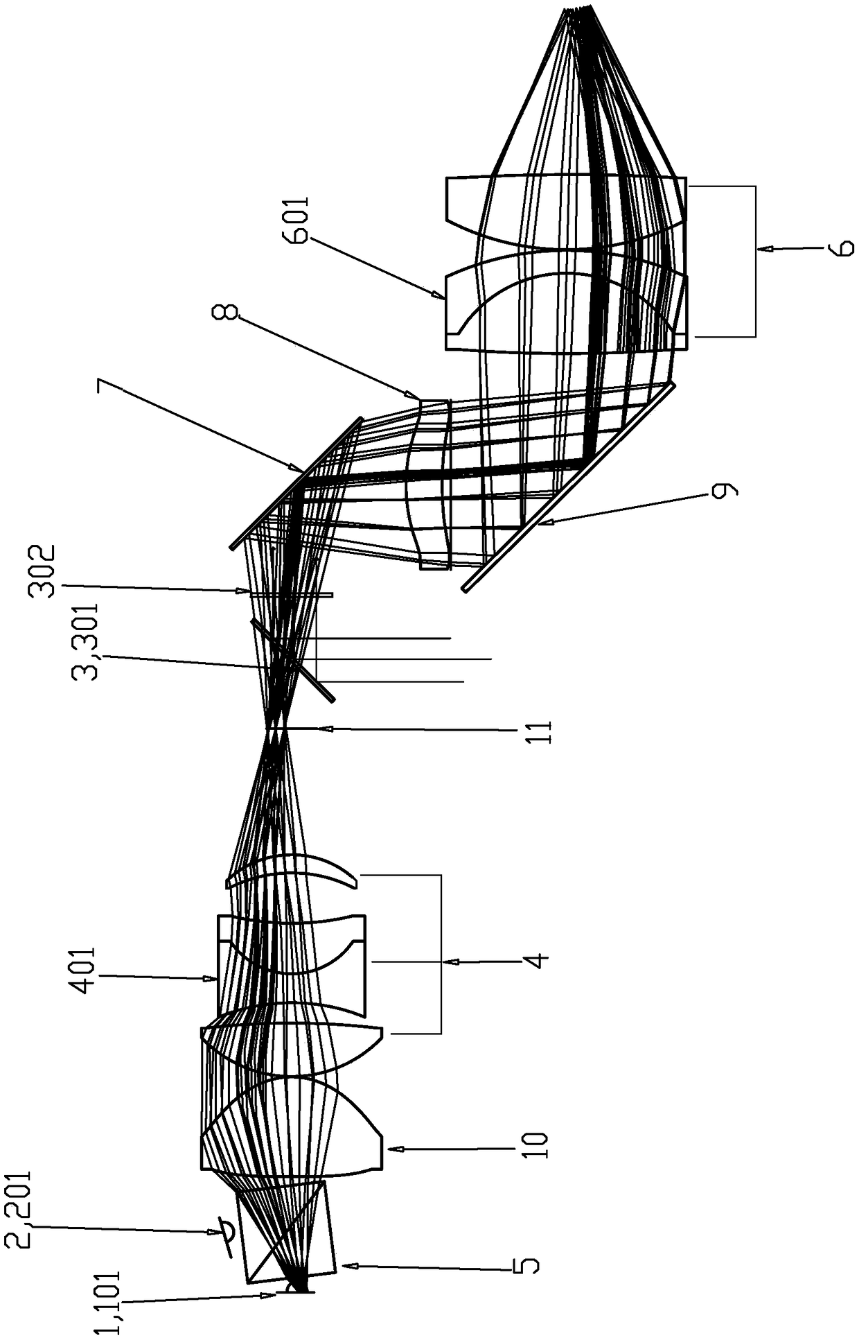
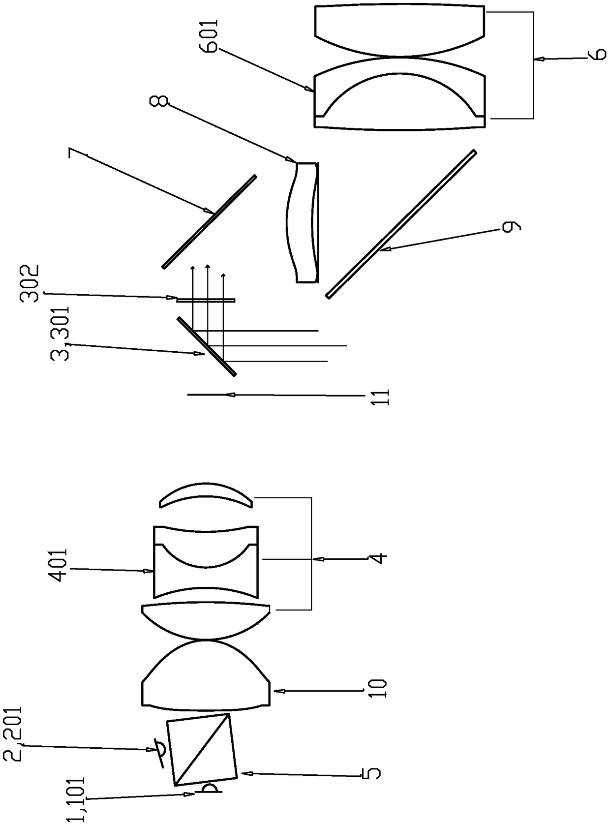
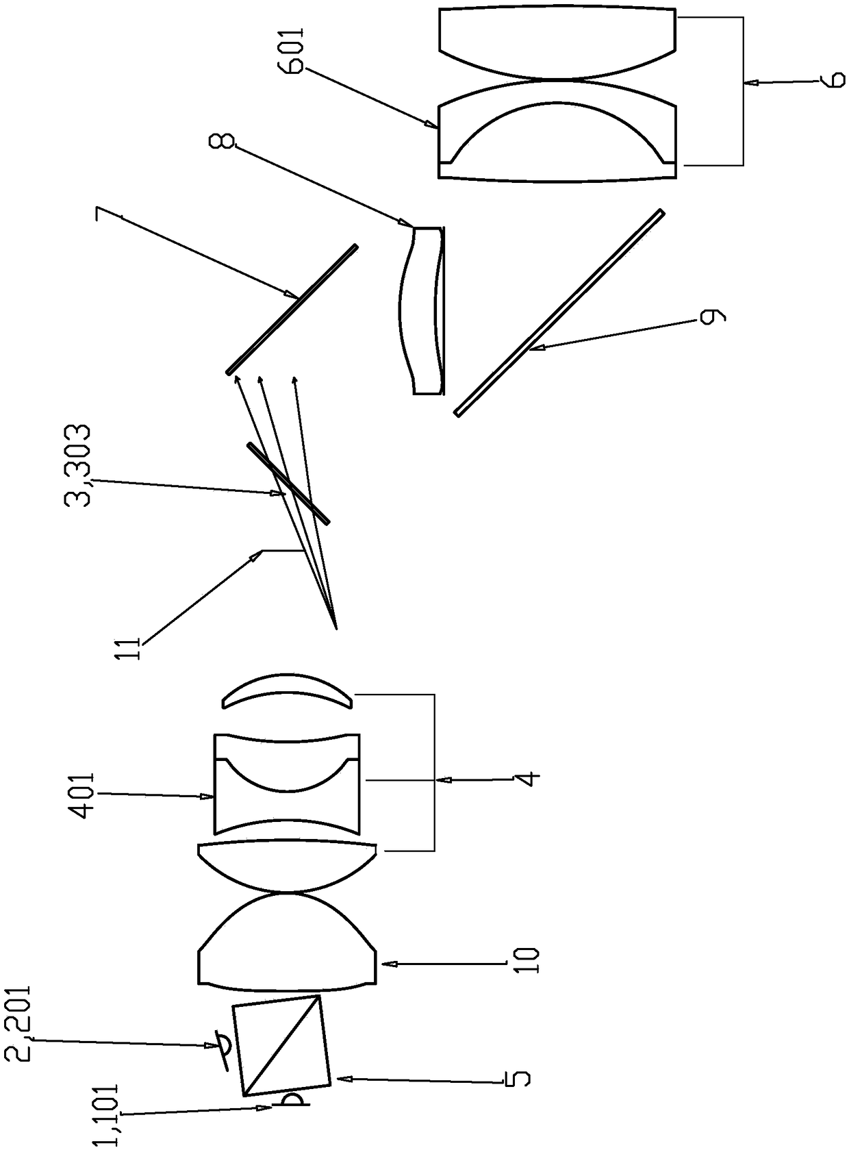
[0033] A kind of anti-ghosting fundus camera lighting system, such as Figure 1 to Figure 6c As shown, from the object side to the image side, it includes a beam splitter, a collimating lens 10, a light collection system 4, a field diaphragm 11, a polarization beam splitter 3, a mirror 7, a field lens 8, and a first polarization beam splitter. 9. The eye lens 6 is provided with a first light source 1 on the left side of the beam splitter and a second light source 2 on the upper side of the beam splitter.

[0034] The first light source 1 may be a white LED lamp 101, and the second light source 2 may be an infrared LED lamp 201, that is, the white LED lamp 101 and the infrared LED lamp 201 are respectively placed as figure 1 The left and upper sides of the beam splitting prism 5 are eccentric ...


PUM


Abstract

The invention discloses an illumination system of ghost elimination eye fundus camera, which comprises the following steps of: sequentially comprising a beam splitter, a collimating lens, a light collecting system, a field-of-view optical waveguide, a polarization beam splitter, a reflecting mirror, a field mirror, a first polarizing beam splitter and a receiving objective lens from object space to image space, a first light source is arranged on the left side of the beam splitter, and a second light source is arranged on the upper side of the beam splitter; the light emitted by the first light source and the second light source sequentially passes through the beam splitter, the collimating lens and the light collecting system to form primary image on the field-of-view optical waveguide, then the light sequentially passes through the polarization beam splitter, the reflecting mirror, the field mirror, the first polarizing beam splitter and the receiving objective lens to form a field-of-view-optical waveguide-like spot is formed in the eye pupil or crystalline lens. Compared with the lighting system in prior art, the illumination system of ghost elimination eye fundus camera has the advantages of simpler structure, more uniform illumination and better effect of eliminating ghost.

Description

【Technical field】 [0001] The invention relates to a lighting system for a fundus camera for eliminating ghost shadows. 【Background technique】 [0002] Since the fundus itself does not emit light, and the diameter of the pupil generally does not exceed 3mm during the day, it is required that the light from the lighting equipment and the light from the imaging equipment pass through such a small aperture at the same time to achieve uniform illumination and imaging without ghosting. Traditional ring lighting requires The illumination source is a ring or an array surface light source plus a ring diaphragm or directly adopts the optical fiber external lighting and the imaging system does not share the lens. If the two overlap, it is easy to produce lens ghosts, which will lead to small imaging pupils, low light efficiency or uneven illumination. Traditional lighting does not use polarizers to eliminate corneal ghosts, but uses small angles. Imaging the light source on the cornea...

Claims


Application Information

Patent Timeline
IPC IPC(8): A61B3/12A61B3/14
CPCA61B3/12A61B3/14
Inventor 费穷肖明志张敏刘雨晴李建华全丽伟
Owner UNION OPTECH
Why Eureka
Try Eureka