Gas shield welding contact tube

A technology of conductive tip and gas shielded welding, which is applied in the direction of electrode accessories, electrode characteristics, welding equipment, etc., can solve the problems of increasing the exhaust gas pressure and working time, increasing carbon dioxide emissions, and protecting the quality of welding seams. The effect of maximum service life, increased utilization, and reduced use and maintenance costs

Pending Publication Date: 2018-08-24
青岛光峰自动化科技有限公司
View PDF0 Cites 3 Cited by
  • Summary
  • Abstract
  • Description
  • Claims
  • Application Information

AI Technical Summary

Problems solved by technology

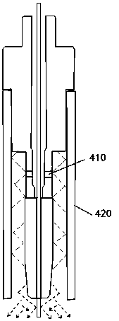
In addition, the inner wall collision reflects the pushing gas and the outer wall 420 to collide with each other to easily form an irregular vortex airflow, thereby generating airflow resistance and consuming the conveying speed due to mutual collision, so it is necessary to increase the pressure and working time of the exhaust gas, thereby increasing the emission of carbon dioxide In the initial welding, it is also prone to failure of the quality of the protective weld seam
[0004] 2. At present, the contact tip of gas shielded welding is made of red copper or alloy copper. The high temperature generated during continuous welding has no conductor to buffer and absorb heat, which accelerates the softening of the material and causes its service life to plummet.
[0005] 3. At present, the gas shielded welding contact tips in the market are all one-piece structure, and the front end has to be replaced as a whole when worn out, and cannot be replaced separately, resulting in waste of materials

Method used


Image

  • Gas shield welding contact tube
  • Gas shield welding contact tube
  • Gas shield welding contact tube

Examples


Embodiment Construction

[0023] The following will clearly and completely describe the technical solutions in the embodiments of the present invention with reference to the accompanying drawings in the embodiments of the present invention. Obviously, the described embodiments are only some, not all, embodiments of the present invention. Based on the embodiments of the present invention, all other embodiments obtained by those skilled in the art without creative efforts fall within the protection scope of the present invention.

[0024] It should be noted that when an element is said to be "fixed" to another element, it may be directly on the other element, or there may be one or more intervening elements therebetween. When an element is referred to as being "connected to" another element, it can be directly connected to the other element or one or more intervening elements may be present therebetween. The terms "vertical", "horizontal", "left", "right", "upper", "lower", "inner", "outer", "bottom", et...


PUM

PropertyMeasurementUnit
pore sizeaaaaaaaaaa

Abstract

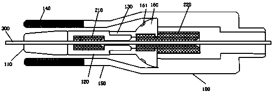
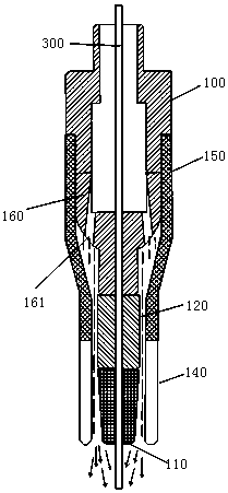
The invention discloses a gas shield welding contact tube which comprises a contact tube body, a gas diffuser arranged at the front end of the contact tube body, and a guide nozzle arranged at the front end of the gas diffuser. Ceramic protectors are arranged in the contact tube body and the gas diffuser. Core holes for allowing welding wires to pass are formed in the ceramic protectors. The welding wires pass through the ceramic protectors via the core holes and are guided out from the guide nozzle. Air holes for allowing protecting gases to pass are formed in the gas diffuser. After passingthrough the air holes, the protecting gases are linear and no interference airflow exists among the protecting gases. The airflow surrounds a soldering point of the guide nozzle to form protective atmosphere. The welding wires are automatically centered by the ceramic protectors, so that abrasion is reduced, heat conduction is isolated, and continuous welding at high temperature is realized. The gas transmission speed is increased and the output pressure of a gas cylinder is reduced by the gas diffuser, so that the utilization rate of carbon dioxide is effectively increased, the discharge is reduced, and the welding quality is improved. The contact tube adopts a split structure, and parts can be replaced as required, so that the using and maintaining costs are reduced.

Description

technical field [0001] The invention relates to the technical field of gas welding, in particular to a gas shielded welding contact tip. Background technique [0002] .The current gas shielded welding contact tip has the following defects: [0003] 1. If figure 1 Shown is the structure of the existing gas shielded welding contact tip. The existing contact tip uses a radial gas diffuser 410. When injecting carbon dioxide gas, it must have a certain pressure before it can be pushed to the welding place of the front contact tip through the collision reflection of the inner wall. In addition, the inner wall collision reflects the pushing gas and the outer wall 420 to collide with each other to easily form an irregular vortex airflow, thereby generating airflow resistance and consuming the conveying speed due to mutual collision, so it is necessary to increase the pressure and working time of the exhaust gas, thereby increasing the emission of carbon dioxide In the initial weld...

Claims


Application Information

Patent Timeline
Patent Type & Authority Applications(China)
IPC IPC(8): B23K9/26B23K9/16
CPCB23K9/26B23K9/16
Inventor 刘福利顾曙光孔令超孙玉娜
Owner 青岛光峰自动化科技有限公司
Why Eureka
Try Eureka