
Eureka
For R&D, Eureka makes reading and utilizing patents & technical documents easy.
Eureka AIR
Designed for self-driven R&D workflows. Generate viable solutions, solve complex R&D challenges, empower your innovation with AI.

Eureka Materials
Designed for material experts only. Revolutionize your material R&D, from search, analyze, to developing new materials.

TechResearch
Generate reliable direction feasibility study reports for your R&D in just a few steps.

TechSeek
Discover and master advanced knowledge NOW. Basics, ideas, possibilities, all at once.

TechMind
As an expert in R&D Theories, TechMind can generates customized viable solutions instantly.

TechRisk
Analyze your overall solution with one click, know your potential R&D risks in advance.

TechMonitor
Get weekly tech updates, stay abreast of the latest tech innovations and key insights.
Environment-friendly geothermal floor capable of improving indoor air quality
A technology for indoor air quality and geothermal floor, applied in the direction of floor covering, modified epoxy resin adhesive, chitin polysaccharide coating, etc., can solve problems such as poor formaldehyde content processing ability, and achieve the effect of ensuring freshness
- Summary
- Abstract
- Description
- Claims
- Application Information
AI Technical Summary
Problems solved by technology
Method used
Image

Examples
Embodiment 1
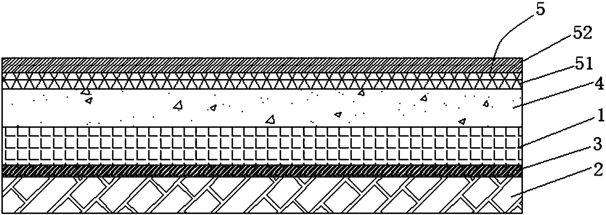
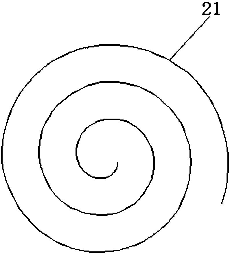
[0032] see Figure 1 ~ Figure 3 , a kind of environment-friendly geothermal floor that can improve indoor air quality provided by the present invention, said geothermal floor comprises: surface layer board 1; Laminated with the surface plate 1, the bottom of the bottom plate 2 is provided with an accommodating groove 21 for accommodating the heating pipeline. A number of heat conduction holes (not shown) are opened on the upper surface of the plate 2, and the heat conduction holes are arranged at intervals along a plane spiral. The inner wall of the trough 21 is sequentially coated with an insulating layer (not shown), a moisture-proof layer (not shown) and an antibacterial layer (not shown) from inside to outside; the upper surface of the surface board 1 is coated sequentially from bottom to top There is a wear-resistant layer 4 and a formaldehyde adsorption layer 5; the adhesive layer includes the following components by weight: acrylic modified epoxy resin: 45 parts, silan...
Embodiment 2
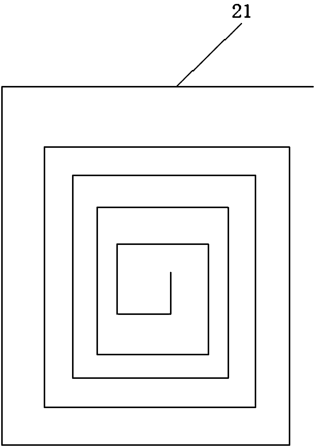
[0042] refer to Figure 4 The accommodating groove is meanderingly opened on the bottom surface of the base plate in a wave shape, and correspondingly, the heat conduction holes are opened on the upper surface of the base plate at intervals along the wave shape. All the other are with embodiment 1.
Embodiment 3
[0044] The adhesive layer includes the following components by weight: acrylic modified epoxy resin: 40 parts, silane coupling agent: 15 parts, methyl cellulose: 25 parts, N-methylpyrrolidone: 5 parts, o-phenyl Dibutyl diformate: 15 parts, graphene: 10 parts, modified ammonium polyphosphate: 20 parts, nano-silica: 10 parts, nano-alumina: 10 parts, methacrylic acid: 5 parts, antioxidant: 1 parts, thickener: 5 parts, curing agent: 5 parts, deionized water: 60 parts. All the other are with embodiment 1.
PUM
 Abstract
Description
Claims
Application Information
 - R&D Engineer
- R&D Manager
- IP Professional
- Industry Leading Data Capabilities
- Powerful AI technology
- Patent DNA Extraction
Browse by: Latest US Patents, China's latest patents, Technical Efficacy Thesaurus, Application Domain, Technology Topic, Popular Technical Reports.
© 2024 PatSnap. All rights reserved.Legal|Privacy policy|Modern Slavery Act Transparency Statement|Sitemap|About US| Contact US: help@patsnap.com