System and method for realizing machine starting denitration operation

A denitrification and steam technology, which is applied in separation methods, chemical instruments and methods, lighting and heating equipment, etc., can solve the problems that the denitrification facilities cannot be put into operation at the start-up stage, lack of SCR inlet flue temperature adjustment means, and boiler efficiency decline, etc. , to achieve the effect of wide application range, convenient implementation and energy saving

Pending Publication Date: 2018-08-28
HUADIAN ELECTRIC POWER SCI INST CO LTD
View PDF10 Cites 6 Cited by
  • Summary
  • Abstract
  • Description
  • Claims
  • Application Information

AI Technical Summary

Problems solved by technology

[0003] At this stage, there is a technology to increase the flue gas temperature at the inlet of denitrification by arranging the SCR reactor between the two-stage economizers. Generally, it is the minimum steady combustion load of the boiler to 100% BMCR working condition, and it is impossible to realize the operation of the denitrification facilities in the start-up stage
There is also a technology to introduce high-temperature flue gas at the inlet of the low-temperature superheater into the flue of the denitrification inlet through the bypass flue to increase the flue gas temperature at the SCR inlet. Baffles are generally not tightly sealed, resulting in large air leakage and reduced boiler efficiency

Method used


Image

  • System and method for realizing machine starting denitration operation

Examples


Embodiment 1

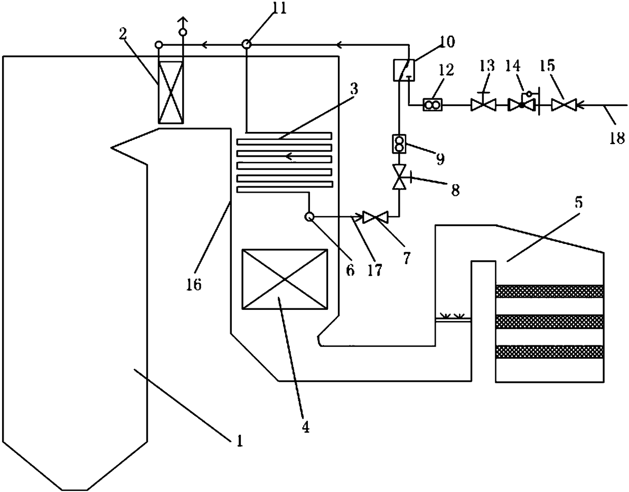
[0030] Such as figure 1 As shown, a start-up and denitrification system is put into operation, including a boiler 1, a final reheater 2, a low-temperature reheater 3, an economizer 4 and an SCR reactor 5.

[0031] A boiler flue 16 is provided on the boiler 1; in the boiler flue 16, a final reheater 2, a low-temperature reheater 3, an economizer 4 and an SCR reactor 5 are arranged in sequence according to the flow direction of the flue gas. The flue gas generated after the combustion of boiler 1 passes through the final reheater 2, low-temperature reheater 3, and economizer 4 successively. After heat release, the flue gas meets the requirements for denitrification and put into operation, and then passes through the SCR reactor 5 to reduce NO X emissions.

[0032] The final reheater 2 is a heat exchange device that uses the steam from the low-temperature reheater 3 to absorb the heat of the high-temperature flue gas generated by the combustion of the boiler 1 to reduce the temp...

Embodiment 2

[0037] According to Embodiment 1, the only difference is that on the low-temperature reheater 3, a low-temperature reheater outlet header 11 and a low-temperature reheater inlet header 6 are arranged in sequence according to the flow direction of the flue gas; The header 6 is a device for uniform distribution of steam flow, and the outlet header 11 of the low-temperature reheater is a device for mixing multiple streams of steam.

[0038] The low-temperature reheater 3 is also provided with a low-temperature reheat steam bypass pipe 17 connecting the low-temperature reheater inlet header 6 and the low-temperature reheater outlet header 11, that is, according to the direction of steam flow, the low-temperature reheater inlet Header 6, low temperature reheat steam bypass pipe 17, low temperature reheater outlet header 11.

[0039] In the present invention, the steam flow direction is opposite to the flue gas flow direction.

Embodiment 3

[0041] According to Embodiment 2, the only difference is that the low-temperature reheat steam bypass pipe 17 is provided with a bypass steam gate valve 7 . The bypass steam gate valve 7 is used to open or close the low-temperature reheat steam bypass pipe 17; when the flue gas passes through the final reheater 2, low-temperature reheater 3 and economizer 4 to cool down, the temperature of the flue gas meets the denitrification According to the requirements of commissioning, the low-temperature reheat steam bypass pipeline 17 is no longer needed at this time, and the low-temperature reheat steam bypass pipeline 17 can be closed at this time, so that steam cannot pass through the low-temperature reheat steam bypass pipeline 17.


PUM


Abstract

The invention relates to a system and method for realizing machine starting denitration operation and belongs to the technical field of coal-fired power station boiler environmental protection. The system comprises a boiler, the boiler is internally provided with a boiler smoke passage, and the boiler smoke passage is internally provided with a final-stage reheater, a low-temperature reheater, aneconomizer and an SCR (Selective Catalytic Reduction) reactor according to the flowing direction of smoke in sequence. According to the system and method for realizing machine starting denitration operation, at the stage of machine starting, a low-temperature reheater steam bypass is adopted to reduce smoke heat absorbed by the low-temperature reheater, adjacent-boiler high-temperature steam is adopted, bypass reheating steam of the boiler is heated, the inlet steam temperature of the final-stage reheater is raised to reduce the heat absorption quantity of the final-stage reheater, and then the inlet smoke temperature of the SCR reactor is raised, and the effective operation of denitration facilities is realized; at the stage of normal operation, according to the actual production requirements, the low-temperature reheating steam bypass and a high-temperature steam pipeline from an adjacent boiler are closed, energy sources are saved, and influence will not be generated to the efficiency of the boiler; and the system is simple and convenient to carry out, furthermore, the investment and operation cost is low, and the system and method for realizing machine starting denitration operation have wide application range.

Description

technical field [0001] The invention relates to a system and method for realizing start-up denitrification and putting into operation, and belongs to the technical field of environmental protection of coal-fired power station boilers. Background technique [0002] Selective Catalytic Reduction (Selective Catalytic Reduction, SCR) refers to the use of reducing agents (such as NH3, liquid ammonia, urea) to "selectively" react with NOx in the flue gas under the action of a catalyst and generate non-toxic Non-polluting N 2 and H 2 O. SCR technology is the most widely used and most efficient flue gas denitrification technology for coal-fired power plant boilers. Affected by the activity of the denitrification catalyst, it is required that the flue gas temperature range of SCR flue gas denitrification is generally 300-420°C. If the temperature is lower than this temperature, the catalyst will be deactivated, so this restricts the start-up of coal-fired power plants and the deni...

Claims


Application Information

Patent Timeline
Patent Type & Authority Applications(China)
IPC IPC(8): F23J15/06F23J15/02F22D1/02B01D53/86
CPCB01D53/8631F22D1/02F23J15/022F23J15/06B01D2258/0283
Inventor 裴煜坤朱跃江建平王建峰李壮柴磊叶伟平
Owner HUADIAN ELECTRIC POWER SCI INST CO LTD
Why Eureka
Try Eureka