
Load arrangement and electrical power arrangement for powering a load

A technology of power and load terminals, which is applied in the direction of electric light sources, circuit devices, lighting devices, etc., and can solve problems such as short-circuit current limitation

Active Publication Date: 2018-08-31
KONINKLIJKE PHILIPS NV
View PDF7 Cites 0 Cited by
  • Summary
  • Abstract
  • Description
  • Claims
  • Application Information

AI Technical Summary

Problems solved by technology

Also, the short circuit current will be limited by this capacitor
[0003] In certain application situations, such lighting devices, especially the way of powering the lighting device (or generally the load), have disadvantages, for example due to the electrical connection between the common electrode layer and the AC voltage source

Method used


Image

  • Load arrangement and electrical power arrangement for powering a load
  • Load arrangement and electrical power arrangement for powering a load
  • Load arrangement and electrical power arrangement for powering a load

Examples


Embodiment Construction

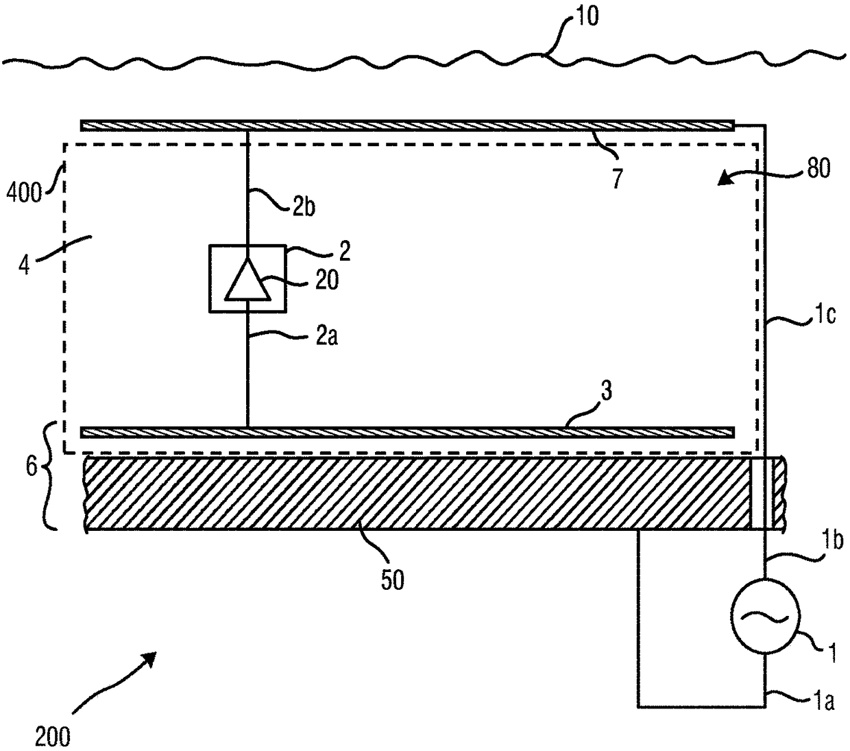
[0050] In the following, the invention will be explained with reference to an application situation in which the invention is used to power UV light sources, especially LEDs, which can be mounted to the outer surface of a ship's hull to combat biofouling. Therefore, before explaining the details of various embodiments of the disclosed subject matter, the general idea and known methods of combating biofouling in such application situations will be discussed.

[0051] WO 2014 / 188347 A1 discloses a method for antifouling of surfaces when said surfaces are at least partially immersed in a liquid environment. The disclosed method includes providing anti-fouling light, distributing at least some of the light through an optical medium comprising a silicone material and / or UV grade (fused) silica, and emitting the anti-fouling light from the optical medium and from a surface. Such anti-fouling solutions are based on UV-C irradiation to prevent the (initial) deposition of micro- and ma...


PUM


Abstract

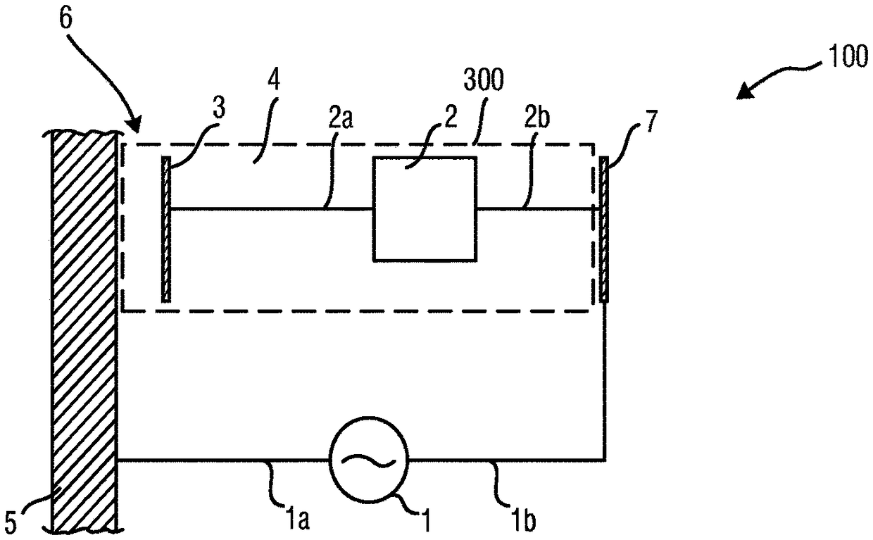
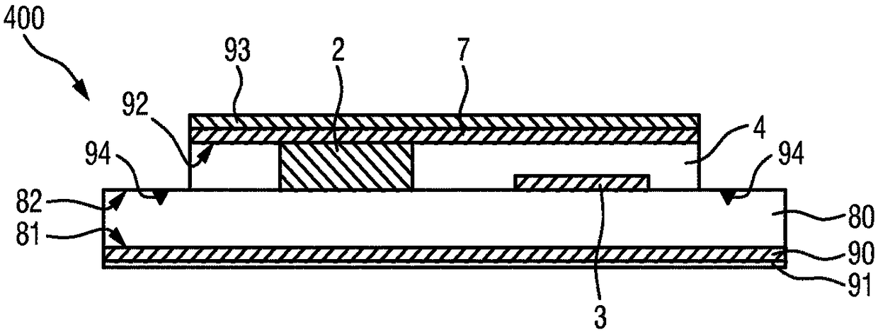
The present invention relates to a load arrangement (400) for use in an electrical power arrangement (200) and for getting arranged at a first external electrically conductive element (50). The load arrangement comprises a load (20) having a first load terminal (2a) and a second load terminal (2b) for being powered by an AC power source (1), a first electrode (3) electrically connected to the first load terminal (2a), and a dielectric layer (4). The first electrode (3) and the dielectric layer (4) are arranged to form, in combination with a first external electrically conductive element (50) representing an outer surface of a marine structure, a capacitor (6) for capacitive transmission of electrical power between the first electrode (3) and the first external element (50). At least one ofthe capacitor (6) and the second load terminal (2b) is arranged for electrical power transmission through water (10) to form an electrical path via the water (10) between the AC power source (1) andthe respective one of the capacitor and the second load terminal (2b). The first load terminal (2a) is electrically insulated from the second load terminal (2b).

Description

technical field [0001] The invention relates to a load arrangement for use in an electrical power arrangement and for being arranged at a first external conducting element. The invention also relates to an electrical power arrangement for powering the loads of such a load arrangement. Background technique [0002] WO 2009 / 153715 A2 discloses a light emitting device comprising a first common electrode, a structured conductive layer forming a set of electrode pads electrically isolated from each other, an interposed between the first common electrode layer and the structured conductive layer A dielectric layer, a second common electrode and a plurality of light emitting elements. Each light emitting element is electrically connected between one of the electrode pads and the second common electrode so as to be connected in series with a capacitor including one of the electrode pads, the dielectric layer and the first common electrode. When an AC voltage is applied between the...

Claims


Application Information

Patent Timeline
Patent Type & Authority Applications(China)
IPC IPC(8): H05B33/08B63B59/04H02J50/05H05B44/00
CPCB63B59/04H02J50/05H05B45/30H05B45/42H05B44/00
Inventor M·H·W·M·范德尔登
Owner KONINKLIJKE PHILIPS NV
Features
  • Generate Ideas
  • Intellectual Property
  • Life Sciences
  • Materials
  • Tech Scout
  • Unparalleled Data Quality
  • Higher Quality Content
  • 60% Fewer Hallucinations
Learn More