A Passively Suspended Double Drive Low Load Crane

A low-load, passive technology, applied in the direction of load-hanging components, shafts and bearings, bearings, etc., can solve the problems of low magnetic flux utilization, reduced positioning accuracy, and excessive magnetic leakage in space, and achieve fast response and transportation speed. The effect of high positioning accuracy and high magnetic field strength

Active Publication Date: 2019-07-26
BEIJING INSTITUTE OF PETROCHEMICAL TECHNOLOGY
View PDF9 Cites 0 Cited by
  • Summary
  • Abstract
  • Description
  • Claims
  • Application Information

AI Technical Summary

Problems solved by technology

However, most of the existing transport cranes are track-contact structures. The equipment has friction and wear during operation and needs to be lubricated. The dust particles generated during its operation have an adverse effect on the cleanliness of semiconductors, and there is also a transmission efficiency. Disadvantages such as low and slow speed
[0003] The automatic material handling system of a maglev trolley described in the patent 201320776620.5 utilizes the principle that the coil is passed through an alternating current to become an electromagnet to realize the suspension and guidance of the device, resulting in a large amount of heat. Due to the lack of reasonable design of the direction of the magnetic circuit, there is a lot of space leakage , the utilization rate of the magnetic flux is low, and the volume of the suspension device is large, resulting in a large power consumption during the operation of the device
In addition, a linear synchronous motor is used to place the rotor on the trolley for transporting materials, and the stator is installed on the track. The operation process causes additional attraction between the trolley and the track, which increases the load and power consumption, and reduces the positioning accuracy.

Method used


Image

  • A Passively Suspended Double Drive Low Load Crane
  • A Passively Suspended Double Drive Low Load Crane
  • A Passively Suspended Double Drive Low Load Crane

Examples


specific Embodiment approach

[0012] The preferred embodiment of the passively suspended dual-drive low-load crane of the present invention is:

[0013] It is mainly composed of the stator part and the mover part. The stator part includes: the frame, the upper magnetic plate, the upper left permanent magnet of the stator, the upper right permanent magnet of the stator, the upper magnetic isolation positioning block, the left L-shaped magnetic plate, and the right L-shaped magnetic plate , Lower left magnetic positioning block, lower right magnetic positioning block, left permanent magnet of stator, right permanent magnet of stator, lower left permanent magnet of stator, lower right permanent magnet of stator, left magnetic guide rail, right magnetic guide rail, left permanent magnet of left guide rail , upper permanent magnet on the left guide rail, right permanent magnet on the left guide rail, lower permanent magnet on the left guide rail, left permanent magnet on the right guide rail, upper permanent mag...

specific Embodiment

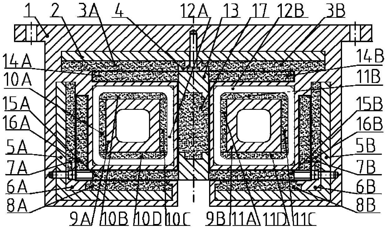
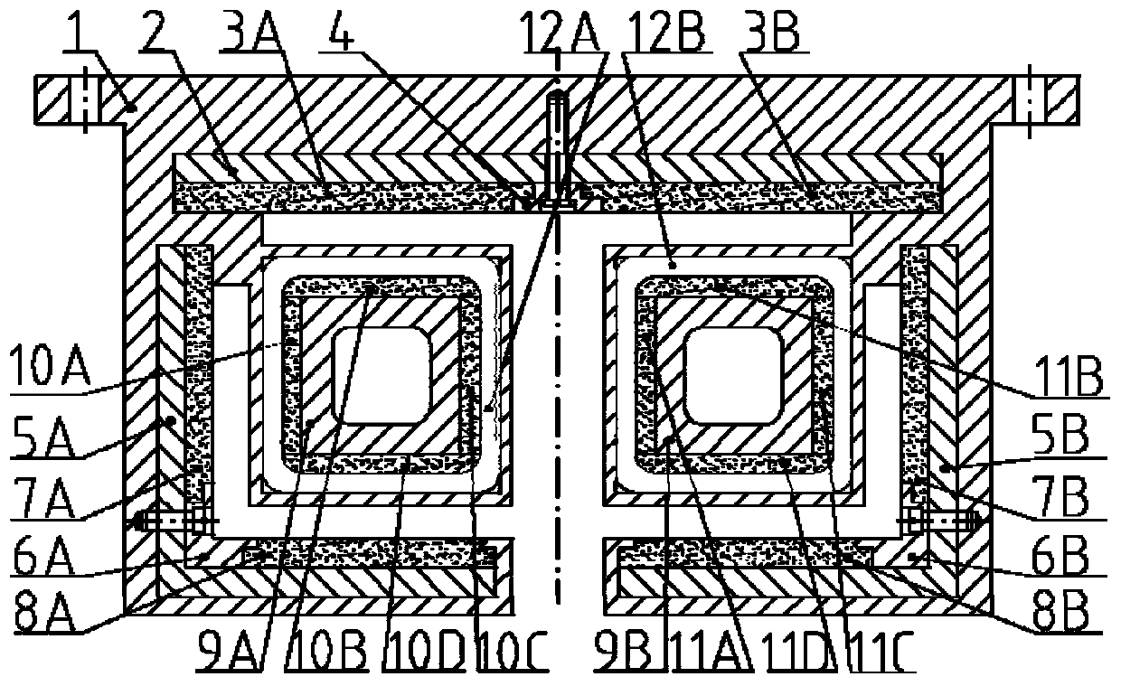
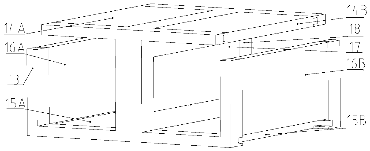
[0020] Such as figure 1 As shown, the passively suspended double-drive low-load crane is mainly composed of a stator part and a mover part. The stator part includes: frame 1, upper magnetic plate 2, stator upper left permanent magnet 3A, stator right upper permanent magnet 3B, upper spacer Magnetic positioning block 4, left L-shaped magnetic plate 5A, right L-shaped magnetic plate 5B, left lower magnetic positioning block 6A, right lower magnetic positioning block 6B, stator left permanent magnet 7A, stator right permanent magnet 7B, stator lower left Permanent magnet 8A, stator right lower permanent magnet 8B, left magnetic guide rail 9A, right magnetic guide rail 9B, left guide rail left permanent magnet 10A, left guide rail upper permanent magnet 10B, left guide rail right permanent magnet 10C, left guide rail lower permanent magnet 10D , the left permanent magnet 11A of the right guide rail, the permanent magnet 11B on the right guide rail, the right permanent magnet 11C o...


PUM


Abstract

The invention discloses a passive suspension double-drive low-load crown block. The passive suspension double-drive low-load crown block mainly consists of a stator part and a mover part; the stator part comprises a frame, a stator permanent magnet, an upper magnetic conducting plate, an upper magnetic isolation positioning block, an L-shaped magnetic conducting plate, a magnetic conducting positioning block, a magnetic conducing guide rail and a square winding coil; and the mover part comprises a movable frame, a mover permanent magnet and a baffle plate. The passive suspension double-drive low-load crown block adopts the square winding coil structure to increase effective length of the coil in a magnetic field, uses double permanent magnets to improve the gap flux density uniformity of the winding coil, and uses magnetic conducting materials to reduce the gap magnetic leakage; and in addition, a driving magnetic flux and a suspension magnetic flux are coupled to form a loop, so thatthe magnetic flux utilization rate is increased. The passive suspension double-drive low-load crown block has the advantages of good gas flux density uniformity, high magnetic field intensity, high positioning precision, high driving force, high transportation speed, compact structure, small size and the like, and can be applied to such high-cleanness working environments as semiconductor transportation.

Description

technical field [0001] The invention relates to a device for linear transportation of semiconductor FOUP materials, in particular to a passively suspended double-drive low-load crane. Background technique [0002] Since the semiconductor process requires avoiding pollution and damage to wafers, it has very high requirements on the cleanliness of the working environment. Therefore, it is necessary to strictly control the number of dust particles in the environment. As a FOUP transmission crane dedicated to semiconductors, its cleanliness during work It is a requirement for product licensing, because the cleanliness of the equipment itself will affect the quality of semiconductor products when working in an environment with high cleanliness, so there is a high requirement for the cleanliness of the semiconductor transportation crane. However, most of the existing transport cranes are track-contact structures. The equipment has friction and wear during operation and needs to be...

Claims


Application Information

Patent Timeline
Patent Type & Authority Patents(China)
IPC IPC(8): B66C9/14B66C7/08F16C32/04
CPCB66C7/08B66C9/14F16C32/0434
Inventor 赵勇马丽梅刘强隋金玲张淞铭吴立志单希林吴波韩明忠
Owner BEIJING INSTITUTE OF PETROCHEMICAL TECHNOLOGY
Why Eureka
Try Eureka