Underground laser detection device

A laser detection, buried technology, applied in the field of detection, can solve the problems such as the upper limit of the number of times/cycle, complicated maintenance, no judgment, etc., to achieve the effect of anti-interference, no false alarm, strong anti-interference, and fast response.

Pending Publication Date: 2018-09-04
安徽中科瀚海光电技术发展有限公司
View PDF6 Cites 0 Cited by
  • Summary
  • Abstract
  • Description
  • Claims
  • Application Information

AI Technical Summary

Problems solved by technology

However, the electronically controlled sensor uses micro-current for monitoring, which is highly sensitive to the moisture and air pressure in the environment, and it is prone to misjudgment. The transmission method is electrical conduction, which has problems such as signal attenuation and large noise.
[0005] In addition, in order to improve the detection effect, the electronic sensor / electronic control detection component has the minimum value of the working current. If it is lower than this value, the component will not work normally, and it is easy to make false alarms and false negatives.
However, in flammable and explosive monitoring occasions, the greater the working current, the higher the probability of causing safety risks
In addition, electrical equipment also has the risk of accumulating static electricity, which undoubtedly brings potential risks to safety production monitoring
[0006] On the other hand, under the dual influence of humidity and temperature, the monitoring equipment buried underground still has the objective problem of aging monitoring sensors, power transmission lines, and signal transmission lines, and cannot effectively monitor for a long time
[0007] 2. Sensors based on chemical principles, on the one hand, they are disposable components, and there is an upper limit on the number of times of use / period;
[0008] To sum up, none of the traditional detection methods can effectively monitor underground pipelines, and there are many problems such as complex structural design, high manufacturing cost, poor detection accuracy, large environmental impact, complicated maintenance, and potential safety hazards.

Method used


Image

  • Underground laser detection device
  • Underground laser detection device
  • Underground laser detection device

Examples


Embodiment Construction

[0032] The structural features of the present invention will now be described in detail in conjunction with the accompanying drawings.

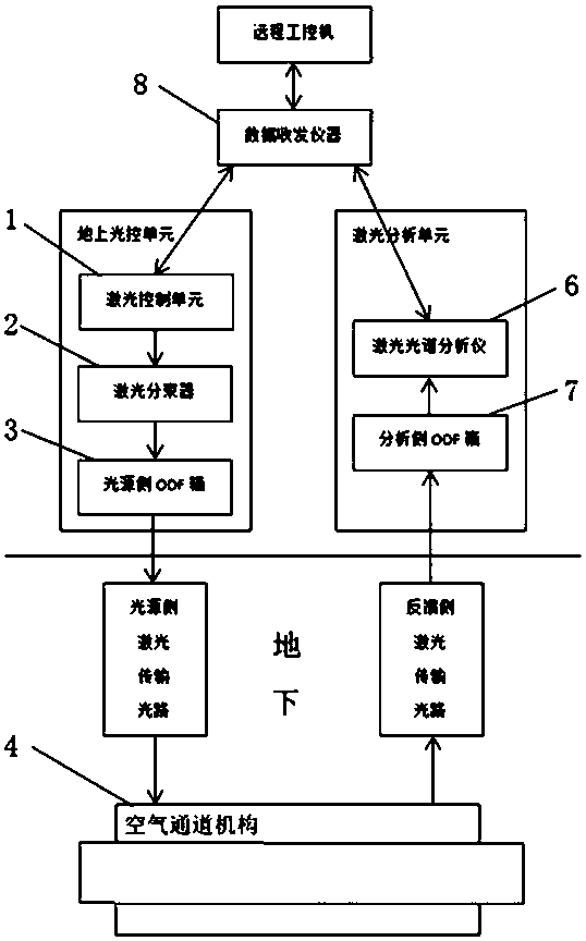
[0033] combine figure 1 , 2 And 7, an underground laser detection device, which is composed of two parts: an aboveground light control unit and an underground monitoring unit. Among them, the ground light control unit is set in the base station and is responsible for generating laser light. The underground monitoring unit is buried underground, and is responsible for transmitting the laser beam generated by the above-ground light control unit to the detection area, and transmitting the laser beam back to the ground.

[0034] see figure 2 Or 7, further speaking, the ground optical control unit includes a laser control unit 1 , a laser beam splitter 2 , and an ODF (Optical Distribution Frame, optical fiber distribution frame) box 3 on the light source side. Wherein, the laser control unit 1 is connected with the ODF box 3 on the light sour...


PUM


Abstract

The invention provides an underground laser detection device, which consists of two parts: a ground optical control unit and an underground monitoring unit, wherein the ground optical control unit isarranged in a base station, and is responsible for producing laser; the underground monitoring unit is buried underground, and is responsible for transmitting a laser beam produced by the ground optical control unit to a detection region, and transmitting the laser beam back to the ground. The underground laser detection device provided by the invention is a piece of optical detection technology-based pipeline detection equipment, and as a monitoring means, the internationally most advanced gas monitoring technology-laser monitoring technology is applied to detection of underground pipelines for the first time by the underground laser detection device. The underground laser detection device is high in sensitivity and fast in reaction speed, is also capable of detecting out tiny leakage immediately in an instant that the leakage occurs, is high in anti-interference performance and has no false alarms and the drift and poison deactivation problem of a traditional methane gas sensor.

Description

technical field [0001] The invention belongs to the detection field, in particular to an underground laser detection device. Background technique [0002] Due to the limitation of the laying environment, the pipelines buried underground cannot be manually inspected regularly. It can only be estimated by means of simulation, and the accuracy is quite inaccurate. Or adopt the method of regular excavation and random inspection. First, the cost of excavation and landfill is high and the cycle is long. Second, safety risks in construction operations are prone to occur during the secondary excavation process. The conventional method is to use electronic instruments to conduct periodic detection on the surface of the pipeline. However, the period from the beginning of the leakage of the pipeline to the spread to the surface is long, the amount of spillage is small, and the detection is difficult. And when the instrument can detect it, or when the problem can be found through macr...

Claims


Application Information

Patent Timeline
Patent Type & Authority Applications(China)
IPC IPC(8): F17D5/02
CPCF17D5/02
Inventor 李幼安
Owner 安徽中科瀚海光电技术发展有限公司
Why Eureka
Try Eureka